With a driveway alarm, you can be sure your property is protected from intruders. The primary reason to get a timely driveway alert is to detect when a vehicle or person enters or leaves your driveway. The most common driveway alarm would detect the smallest of figures – both humans and animals as they often come with passive infrared (PIR) motion sensors that can detect a figure coming towards your driveway and can alert you via chime that sounds instantly.
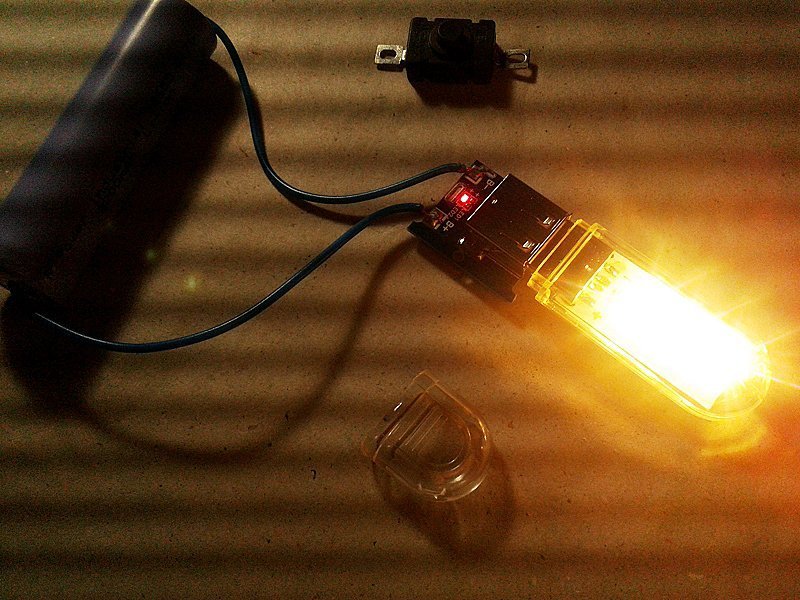
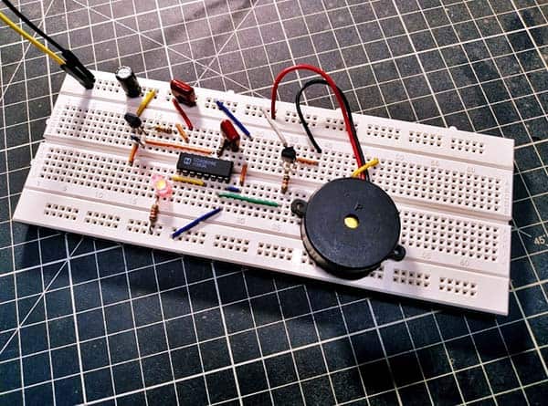
Inspired partly by a commercial driveway alarm system (see the lead photo), I couldn’t resist having a go at building a budget driveway alarm. To keep the costs down, I tried to use commonly available and cheap electronics components where possible. Here is my first version schematic with all constituents in situ.
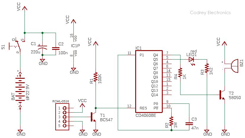
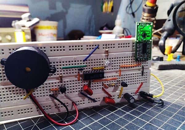
At the heart of this little design is a mini Doppler radar motion detector module RCWL-0516. The next key component is the 14-stage ripple-carry binary counter/divider and oscillator CD4060BE. The entire electronics of this driveway alarm are powered by a single 6F22 9V battery (https://en.wikipedia.org/wiki/Nine-volt_battery).
The doppler radar module has a 5-pin interface but only three connections out of that five are needed here (VIN-OUT-GND). The VIN pin is a positive power supply input, accepting any DC voltage from 4V to 28V. The OUT pin is a 3.3V logic level output pin. When the sensor detects a moving object, it will deliver a logic-high (H) level output through this pin for a finite time (two full seconds).
The CD4060 IC also has a wide operating voltage from 3V to 18V. Its internal clock oscillator can be set by using an external resistor and an external capacitor (R2 & C3 in this design). The formula to set the RC oscillator frequency is F= 1 / (2.5*R2*C3), where F is in Hz, R is in ohms and C is in Farads.
A HIGH level on RES resets the CD4060 counter. As you can see in the given schematic, the RES pin (Pin 12) is routed to Vcc through R1, hence IC1 remains inactive in standby mode. When there’s an output signal from the radar sensor module, T1 gets activated and pulls down the MR pin LOW. As a consequence, the driver transistor T2 enables the active piezo-buzzer BZ1 quickly, and the buzzer starts beeping in a rhythmic manner. The visual indicator LED1 starts flashing at a slow rate, as well.
Although it needs a bit of skill and patience, you should do some tweaks to get the best from your RCWL-0516 radar module. First, you have to add an SMD capacitor (C-TM) in parallel with the onboard 10nF timing capacitor to extend the default (2s) trigger time period. Doubling the capacitor value will double the delay time. For more details https://github.com/jdesbonnet/RCWL-0516/
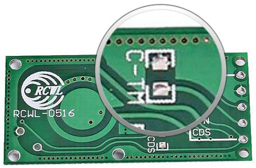
Next, note that as it appears the module has a ‘field of vision’ which means that the best movement detection is achieved when an object is moved in front of its ‘active’ face i.e., the upper side with RCWL-9196 chip (see below).

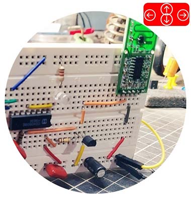
While testing your prototype, after mounting it upright in the center of a hall, you can walk in and out of that hall (about five to nine meters away from the setup) slowly to get an instant ‘proximity’ response (the smaller the distance the less reliable the response seems to be). It might be interesting, rapid movement of any object in front of the setup does not trigger much response!
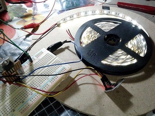
I just spent an afternoon making the quick test prototype on a standard breadboard.
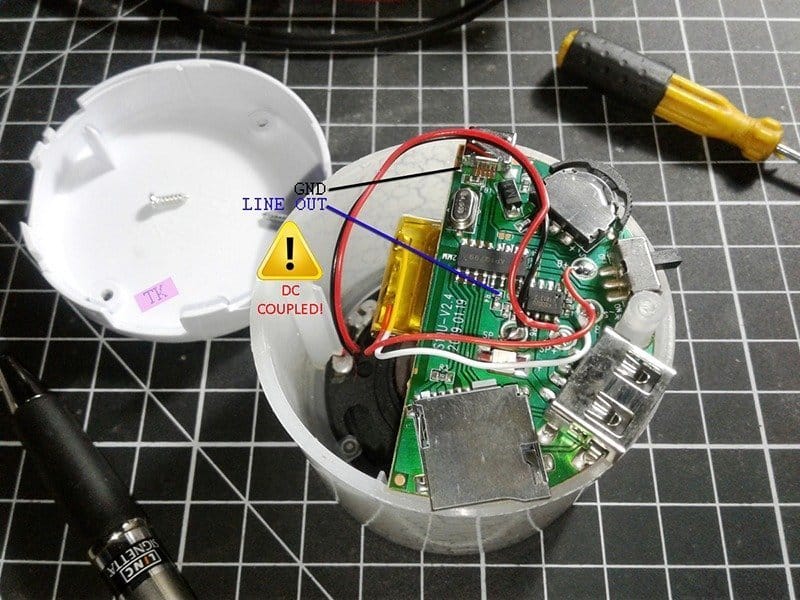
I had a pair of the RCWL-0516 radar modules on hand, so after I got this project working with one, I used the other to conduct a destructive teardown. What I found at that time was interesting (perhaps a theme for a new post). If someone were really interested, there may be some potential for hackability there!
You could built a driveway alarm in several different ways, but the microwave Doppler Radar idea has got to be the coolest. When it comes to motion sensors, each has its pros and cons. So, what are the advantages of the microwave sensor over the passive infrared motion sensor?
- Not influenced by ambient temperature
- Wide detection range
- Less false trigger
The microwave sensor is perfect if you have a large space and area with awkward spaces like corners such as your driveway while the passive infrared sensor is perfect if you have an enclosed space such as hallways and walkways. Now that you have to find out which motion sensor is good for your driveway alarm. Both can be used in this design as the alarm circuitry merely needs a logic-high level input to wake up!
For now, I’m really happy with how this project came out. If you are considering building this driveway alarm, I would encourage you to use a rigid and waterproof enclosure as it helps to make a robust outdoor alarm device. The enclosure must have flag pole clamps on the back so that it can securely be mounted on a lamppost grounded in concrete. Also be careful about adjusting the ‘angle’ of the device so that you don’t get any false alarm. Note that your driveway alarm would become a worthless idler if not installed properly.
Furthermore, you can place your driveway alarm wherever you want, but it will be quite good to install a second piezo buzzer or magnetic buzzer (in parallel with the existing one) inside your home where you can quickly get to hear the alarm. Remember to choose a mighty (>=125dB) sounder which is loud so it will easy to hear. If it is necessary to make the cables invisible, you should bury them underground and ensure cable protection with conduits. It does not require any professional help as you can probably do that.