Electronics are sensitive to extremes of humidity, and moisture seems to be a key contributor to a variety of electronic-system failures. Conductivity in devices can be modified by high humidity, which can lead to corrosion and malfunction. Condensation can also be a real problem. Taking these into account, Dew Sensors are vital for protecting sensitive electronics devices from dew. I had developed a number of hobby-level dew sensor projects. The first one was published by EFY magazine (print edition). But that was a long time ago – I think it was in year 2011 (https://www.electronicsforu.com/electronics-projects/dew-sensor)!
When I recently googled some cheap weather sensors and others, I accidentally came across another resistive humidity sensor HR202. Surprisingly, the sensor is available not only as a separate component, but also in the form of a prefabricated module. After that, I bought a collection of them from an online store – just curious, that’s why!
Today you can find a variety of capacitive and resistive humidity sensors for medical and everyday applications. My talk here is only about resistive sensors but note that resistive sensors work on the similar principle to capacitive sensors, where electrical change is measured to produce a value for relative humidity. However, the sensor mechanism is different i.e., resistive sensors use a moisture-absorbing (hygroscopic) material similar to the capacitive system, but the difference is that the measurement is of the resistance change in the material rather than the capacitance. The key benefit of a resistive humidity sensor is the high surface-volume ratio which allows it to measure humidity changes in the environment up to 90% relative humidity (RH) at room temperature. Further reading https://www.digikey.com/en/articles/humidity-sensors-and-signal-conditioning-choices
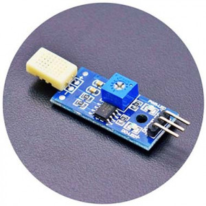
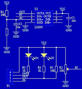
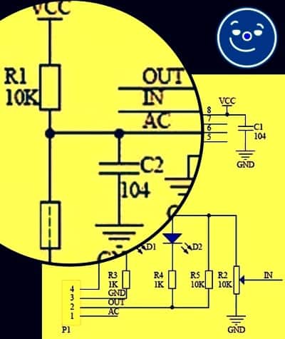
When returning to the HR202 Resistive Humidity Sensor module, it’s a simple piece of electronics centered around the quite popular dual-comparator LM393 IC. See below for a web circuit diagram of it.
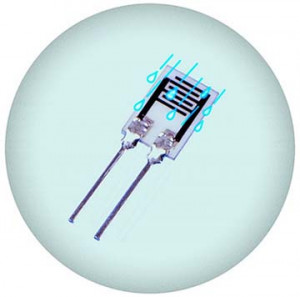
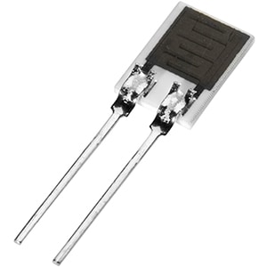
As pointed above, this inexpensive module is based on the HR202 resistive humidity sensor made from organic macromolecule materials. See its datasheet https://www.elecrow.com/download/HR202%20Humidity%20Sensor.pdf
This particular module picks up changes in the resistance value of the humidity sensor element in response to the change in the humidity and delivers a digital-level (high or low) output. The onboard multiturn trimpot can be used to set the detection threshold level. Two onboard LEDs indicate power input and signal output statuses.
Specifications:
- Operating Voltage: 5V DC/3.3V DC
- Operating Current: 15mA
- Humidity Range: 20 to 95%RH
- Output (Digital): 0V (L) or 5V (H)
LM393 IC consists of two independent precision voltage comparators with open-collector outputs (open-collector denotes uncommitted collector of a grounded-emitter n-p-n output transistor). The maximum output sink current is around 16mA but after 10mA, it starts to get into current limiting. So, it’s always good to stay below 5mA to keep away from the current limit and minimize power dissipation. This, however, calls for an external BJT or MOSFET to sink higher currents. LM393 Datasheet https://www.onsemi.com/pub/Collateral/LM393-D.PDF
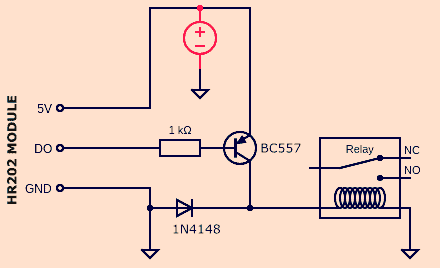
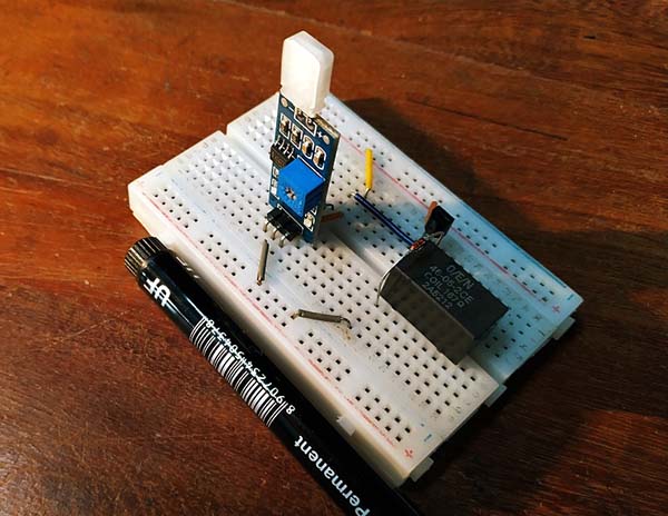
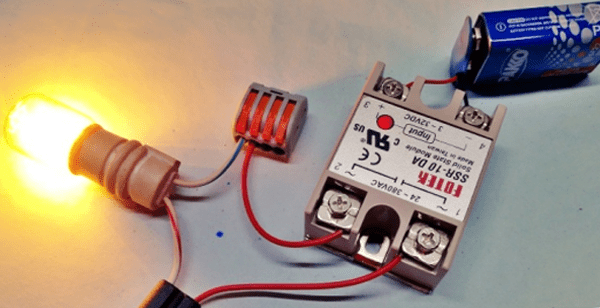
In the following circuit, digital output of the HR202 module drives a small 5V/167Ω O/E/N relay through one PNP transistor BC557. This crude humidity switch can be used to ensure that the relevant equipment works in the appropriate environment.
How to check/calibrate your humidity sensor? Find out through this post https://www.allaboutcircuits.com/projects/how-to-check-and-calibrate-a-humidity-sensor/
A resistive humidity sensor measures the change in electrical impedance of a hygroscopic medium. Its resistance changes inversely with humidity. The impedance change is typically an inverse exponential relationship to humidity. Note that most resistive humidity sensors use symmetrical AC excitation voltage with zero DC bias to prevent polarization of the sensor. The resulting current flow is converted and rectified to a DC voltage signal for additional scaling, amplification, linearization, or A/D conversion. Nominal excitation frequency is from 30 Hz to 10 kHz. Recommended excitation frequency of HR202 is from 500 Hz to 2 kHz.
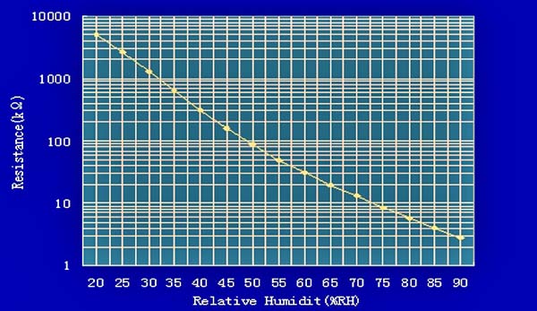
See the impedance performance of HR202 at 25°C , 1V AC, 1kHz. The impedance range varies from 1KΩ to 10MΩ.
In the datasheet, you can see the caution “Avoid polarization, driving voltage or current should be 100% alternative“. But in this particular HR202 module, the HR202 sensor is roughly wired as the part of a potential divider that’s biased by 5V (or 3.3V) DC. Strikingly odd!
Actually, in this module, we just feed the sensor a fixed voltage and use one comparator to check against a reference voltage set by the trimpot to make the final digital out pin High or Low. That is obviously against the warnings and suggestions on the official datasheet. Based on my observations, I’m sure it will work to some extent but I can’t figure out how to use a resistive humidity sensor aright just with a fixed dc voltage and a comparator!
What I learned is that in order to properly use the sensor we need to set up an LCR alternative-current bridge.
https://www.ietlabs.com/pdf/GenRad_History/A_History_of_Z_Measurement.pdf
Block diagram of a similar concept chosen to instrument the sensor appears in the below figure. Thanks to Texas Instruments for providing the instigating Application Report (SNOA720B–August 1981–Revised May 2013).
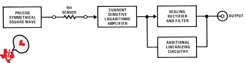
Here, an amplitude stabilized square wave that is symmetrical about zero volts is used to provide a precision alternating current through the sensor, satisfying the requirement for a zero DC component drive. The current through the sensor is fed into a current sensitive (for example, the input is at virtual ground) logarithmic amplifier, which linearizes sensor response. The output of the logarithmic amplifier is scaled, rectified, and filtered to provide a DC output that represents relative humidity.
It is worth noting that the detailed circuitry requires a number of ICs and other discrete parts. So, I still need time and money to move this good idea forward. Maybe I will come back in the near future with a unique solution. Stay tuned!
Tailpiece: Does it mean the HR202 module is a worthless piece of electronics? No, not all, moderately useful, handy, and very cheap. However, over time one learns the shortcomings and finds ways to improve!
hello, I would like to ask you to explain to me how to connect the humidity sensor HR202 5V to the fan in the bathroom? simple schematic please. thank you for your reply