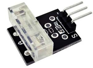
Recently I came across a dirt-cheap knock sensor module labeled as Keyes KY-031 Knock/ Impact/Hit Sensor. The other day I bought a couple of those modules from an online store.
It’s pretty small and easy to use so that you can think of several good applications based on Keyes knock sensor. Frankly, this got me thinking about how to build a new door/window knock sensor. Now I can tell you from my own experience how that idea works!
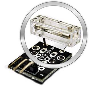
This KY-031 is a variation on the everyday vibration sensor modules, except that the sensitivity is much reduced. It is designed to register a knock or hit on for example a door or window.
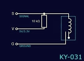
As you can see in the below simplistic circuit diagram drawn by me, the 10K resistor in the module is wired between S and V to pullup the sensor signal output line S to +5v (or 3.3V) in idle state. When knocked it gives a short falling (H→L) output pulse on S. The knock sensor part is somewhat insensitive and needs a very strong knock for the spring (sensing element) inside to move and touch the metal contact located next to it.
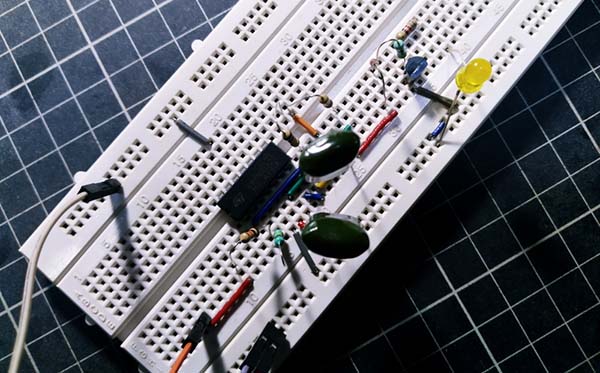
Following is an ultra-simple KY-031 knock sensor module tester circuit centered on the venerable 555 timer IC. In the circuit, the NE555 (IC1) is configured as a ‘textbook’ monostable multivibrator, but it has an open-collector output line for easy interfacing with any 5V/3.3V/3V microcontroller. The tester runs on a standard 6F22 9V battery. Actually, the recommended working voltage of the KY-031 knock sensor module is in 3.3V to 5V range. However, it can just as safely be powered by the 9V battery in this design.
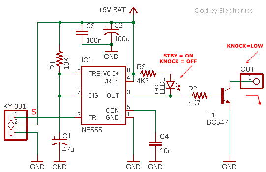
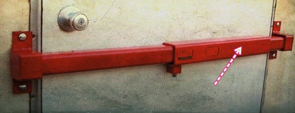
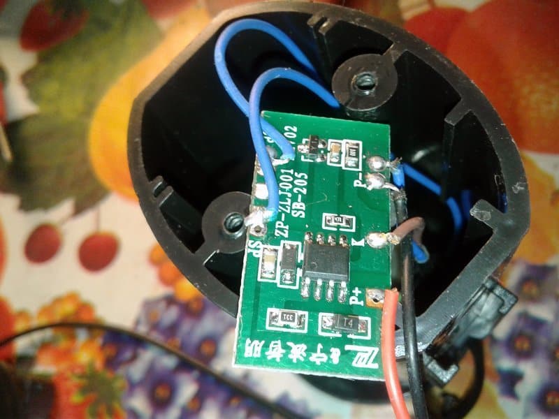
Without any other major components being added, you can use this little tester as a door/window knock sensor alarm as well just by wiring one active piezo-buzzer between its +9V and OUT rails. And then, mount the enclosed prototype on the zombie-arm of your front/back door (see below). If so, it can quickly deliver an audible alert in case of a knock/hit. Note that the aural signal lasts for a finite duration set by the in-circuit value of the timing capacitor C1, and the timing resistor R1. Now is the time to recall the formula T = 1.1 x R1 x C1.
I tested my simple knock sensor alarm concept by using a bit old 9VDC/25mA mechanical buzzer (75dB, 400Hz) I had on hand (https://www.jameco.com/Jameco/Products/ProdDS/24872.pdf).

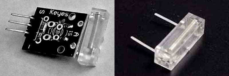
The knock sensor element primarily consists of a central spring attached to one connection terminal, and a second connection terminal located aside in its close vicinity. When sufficient force is transferred to the sensor, the spring moves momentarily touches the second connection terminal, and makes a short circuit between the connection terminals.
At this point, it’s also worthy to notice that the positioning of the knock sensor module is very important. Generally speaking, the knock sensor element should be physically located as close as possible to the area being monitored. Otherwise, the impact being detected may be dampened by other structural parts in your installation!
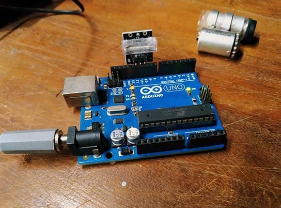
Most Arduino lovers may now look for a way to interface with this little knock sensor module to make the Arduino more responsive to a knock detection input. Although there’re countless online tutorials available on this common theme, I’d like to share my idea too, perhaps in a different way to achieve the same results.
Here is a simple snippet of Arduino Sketch that you may find when looking for this topic online. It monitors the knock sensor output (S) wired to pin12 of an Arduino Uno. When you gently hit the knock sensor the onboard LED on pin 13 wakes up and stays lit for 3000ms.
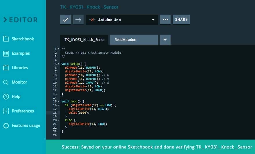
View & Download https://create.arduino.cc/editor/tekmonkz/275039b7-78d7-40cf-94a4-6d973d60a641/preview
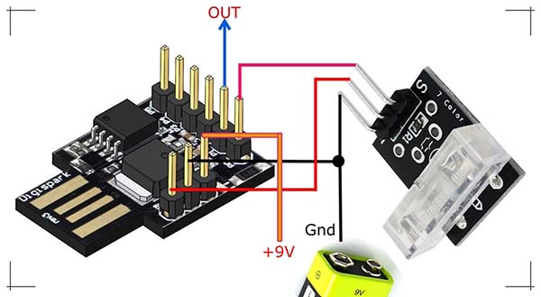
Next is about a simple try-out on the Digispark platform! As depicted in the below diagram, the first I/O (P0) of the Digispark Attiny85 development board reads the knock sensor output, and the second I/O (P1 with onboard LED) delivers a 6000ms long logic-high (H) signal when the system detects a sensible knock. The P1 output can be used to control a relay, buzzer, or lamp with the aid of a driver transistor (BJT or MOSFET). In the experimental runs, the common 6F22 9V battery was used as the power source.
See the code:
int KnockSensor = 0;
int AlertDrive = 1;
int value = HIGH;
boolean Alert = false;

unsigned long LatestKnockTime;
int TriggerTime = 50;

void setup ()
{
  pinMode (KnockSensor, INPUT) ;
  pinMode (AlertDrive, OUTPUT);

}
void loop ()
{
  value = digitalRead (KnockSensor) ;

  if (value == LOW)
  {

    LatestKnockTime = millis();
    if (!Alert) {
      digitalWrite (AlertDrive, HIGH);
      delay(6000);
      digitalWrite (AlertDrive, LOW);
      Alert = true;
    }
  }
  else
  {
    if ( (millis() - LatestKnockTime) > TriggerTime  &&  Alert) {
      digitalWrite (AlertDrive, LOW);
      Alert = false;
    }
  }
}
Going Further…
So, it looks like this Keyes KY-01 Knock Sensor Module will work fine for Arduino projects. Using the setups demoed above I was able to detect hard knocks on wooden doors and metal frames. But in order to keep the switch bouncing down to a dull roar, I’ve to tweak my crude codes to clean up the noisy knock sensor signals.
When the contacts of any mechanical switch/sensor bang together they rebound a bit before actual settling, causing a bounce. Debouncing, of course, is the process of removing the bounces, of converting the beastly realities of the analog world into pristine digital beats. Both hardware and software debouncing solutions exist, though by far the most common are those done in a snippet of code. Software debounce routines range from utterly simple to extremely sophisticated algorithms. Simple, right? Maybe not. More on this later.
I also have a plan to extend this Arduino knock sensor project idea through a Wemos D1 R2 Wi-Fi (ESP8266) development board lying around. Stay tuned!
Is there any way to just remove the sensor part itself (the enclosed spring section) from it’s mini board and directly solderit to a Uno or Mini to make a project more compact?
Sandy: Yes, you can, but you need to employ software denouncing in your Arduino sketch! Further reading https://reference.digilentinc.com/learn/microprocessor/tutorials/debouncing-via-software/start