Wikipedia says the Lavet-type Stepping Motor is a special kind of single-phase stepping motor widely used as a drive-in electromechanical clock. Aside from clock drives, there are many variations of Lavet’s concept, and one example are types of dashboard instruments in cars (https://en.wikipedia.org/wiki/Lavet-type_stepping_motor).
The French engineer Marius Lavet (born in 1894 in Clermont-Ferrand, France) is generally considered to be the inventor of the micro-stepping motor known as the Lavet Motor. At the time he submitted his request for a patent (on September 28, 1936), he had over 70 variations of his invention (his patent was granted in 1937). The most common variation can be seen in almost every quartz clock on the market today.
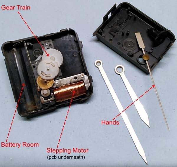
Note that the key components in a quartz clock are the power source (battery/cell), a printed circuit board (PCB) which principally holds one quartz crystal resonator and an integrated circuit, the stepping motor, the gear train, and ultimately, the hands, and display.
I’ve got a Lavet-type stepping motor!
Recently one of my wall clocks stopped, and it’s not easy to get a replacement quartz clock engine that fitted in with the chassis. After a detailed inspection of the quartz clock engine, I found that the metal contacts used for the electrical connection between the battery room and the printed circuit board were clogged, causing the clock to become inactive.
Even though the issue is pretty easy to resolve, I decided to scrutinize its internal mechanism and learn more about the micro-stepping motor before finalizing the repairs. So, I completely dismantled the quartz clock engine. It’s actually a feasibility exercise aimed at hacking the existing Lavet motor rather than building/buying a new one. It is also true that I was a little reluctant to try to repair my wall clock. Oh, sometimes I’m too lazy!
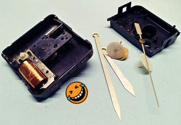
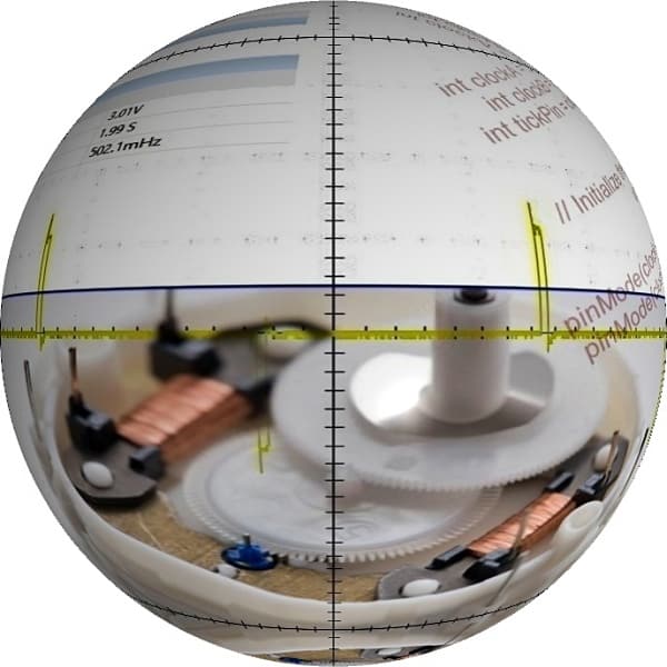
The core part of this Lavet-type stepping motor, which seems similar to a solenoid at a glance, consists of a flat stator with an inductive coil wrapped around an arm. Between the arms of the stator lies the rotor which consists of a circular permanent magnet with a pinion gear attached to the top of it. The pinion gear coupled with other gears moves the clock hands. As observed, the motor works by alternating the polarity of the current in the stator coil with a pause between the polarity changes while the rotor moves to its reluctant position.
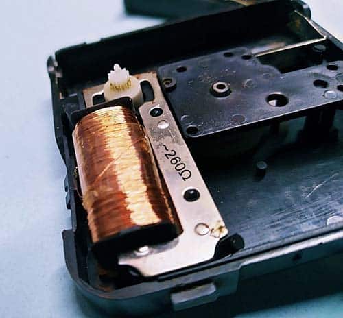
My solenoid has an onboard resistance close to 260Ω. So, given a battery voltage of 1.5V the maximum current draw then would be roughly 6mA. Recall at this point that a bipolar signal is used to drive the solenoid (see the random oscillogram below).
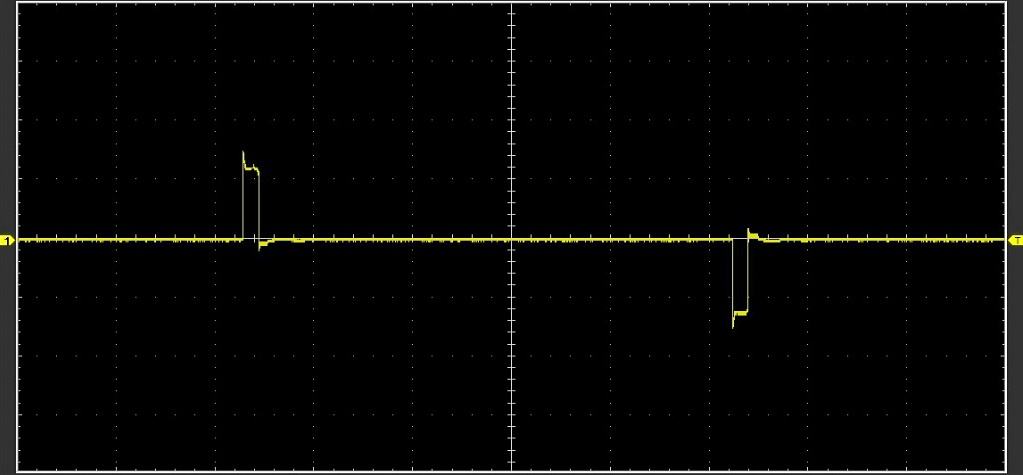
Here’s the drive signal we’re looking for. The output waveform consists of alternating pulses with a peak-to-peak voltage (Vpp) circa 3V.
Just another small stepper motor to tinker with?
If we do a detailed search on Google, we can see innumerable Lavet motor hacking pointers and project ideas. We can also see clever hacks in the form of exotic wall clocks and wristwatches often driven by external microcontrollers. So, now is our turn!
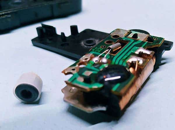
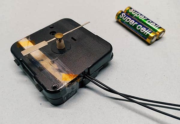
In order to mod an analog quartz clock, first off you need to solder two thin insulated wires to the stepper motor contacts in the printed circuit board. Needless to say, you have to remove the battery and take apart the mechanism until you have clear access to those contacts (to get to the circuit board most of the gear train has to be removed).
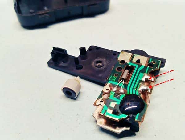
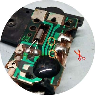
The stepper motor contacts should then be isolated from the existent driver circuitry by cutting the circuit tracks as shown in the below figure. Keep in mind, that this is just a mere pointer, your circuit tracks may be different.
Finally, try to route the wires through a slit made in an appropriate spot on the case so that other ends of the wires are easily accessible from outside. Be mindful of the delicate geartrain in the mechanism, and try not to obstruct it with your new wires. And of course, don’t forget to put everything back on when you’re done (much easier said than done – haha).
In short:
- The clock engine will need to be taken apart to access the electronics inside.
- The circuit board and battery support are no longer necessary. But you can save the circuit board as it may be useful in the future.
- The coil contacts need to be isolated from the rest of the electronics and wires soldered to them so they can be driven by an external source. To do this, just cut the circuit tracks near the drive coil to isolate the other circuitry, solder a thin insulated wire to each coil contact and take them out through a tiny slot made in the case, or via the battery room if possible.
- At last, set everything back on and put back the case together.
More to come soon!
Well, now you’ve an externally controllable quartz clock engine with a Lavet-type stepping motor at its core. I recommend you test the hacked clock engine prior to making any serious projects with it, so you can know right away if you’ve got things working right or not. Soon I will add some interesting stuff here, so stay tuned for the succeeding part of this article. I will be writing it up in due course, but it’s early days!