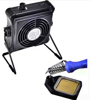
 Recently I have been experimenting with a Chinese solder fume extractor and was interested in using a commonly available BLDC cooling fan to build a close replica of that pretty cute gizmo. Since I have just refilled my analog components drawer with a large collection of discrete parts it would seem sensible to use far-famed NAND Schmitt Trigger IC to control the fume extractor fan. I encourage you to try this little project and stay tuned as it has some further design revisions that add features over and above the basic design I have implemented!
Okay, now I will show you how to make a small solder fume extractor to keep the air in your workbench fresh when soldering. This is the schematic diagram (v1) of the simple solder smoke extractor:
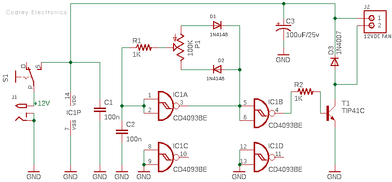
As you can see here, at the heart of this circuit is a quite popular Quad 2-Input NAND Schmitt Trigger IC – the CD4093BE (IC1). In this circuit, first gate (IC1A) of IC1 forms a low-frequency PWM generator as wells as alters the duty cycle as you turn the shaft/knob of the 100K potentiometer (P1) thus varying the speed of the BLDC cooling fan connected to the socket J2 (12VDC FAN). Actually, the potentiometer is used to vary the charge-discharge cycle of the 100nF timing capacitor (C2). Needless to say, this circuit can be used as a simple PWM controller for 12VDC cooling fans and common motors up to several amperes, depending on the transistor chosen for the fan driver transistor T1 (TIP41C).
The second gate of IC1 (IC1B) is wired as a buffer to drive the final driver transistor T1, while inputs of its remaining two gates (IC1C & IC1 D) as they’re not in use at this time. Anyway, you can ungrounded them both for making a parallel connection with the second gate (IC1B) to boost the drive current level. Further Pin 1 of the IC1 can be used as an external enable input – this is a common practice, hence hardly needs any explanation!
The circuit is designed to be powered by a 12VDC switch mode power supply (12V SMPS) capable of catering at least 500mA current through its output. If you want your final model really portable, then you can use a 1S or 2S Li-ion or LiPo battery together with a suitable dc-dc boost converter module (and a charger module) as the built-in power source.
The 12V 80mm x 80mm cooling fan is a type commonly used in desktop computer cabinets and power supply units. I just bought a cheapo fan and a pair of fan grills from an Amazon seller. The fan has only two wires (red and black) for positive and negative 12VDC input.
Frankly, my cooling fan is beautiful but not particularly powerful, so I have installed it close to the solder smoke to function well.
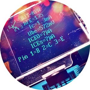
Likewise, I really don’t think the mighty TIP41C transistor is necessary for this circuit, but I opted it as the fan driver just because I have a bunch of them on hand at that time (maximum current consumption of my cooling fan is well under 180mA only). So, you can try any other appropriate driver transistor, if you know what you are doing.
Tech & Shop Links
- CD4093BE Datasheet https://www.ti.com/lit/ds/symlink/cd4093b.pdf
- TIP41C Datasheet https://www.st.com/resource/en/datasheet/tip41c.pdf
- PC Cooling Fan Seller https://www.amazon.in/Electronic-spices-Cooling-Cooler-Radiator/dp/B081NQ4RPG
- 12V SMPS Seller https://robu.in/product/hlk-5m12-12v-5w-switch-power-supply-module/
- 12V SMPS Datasheet https://robu.in/wp-content/uploads/2020/02/5W-series-power-module-V2.3.pdf
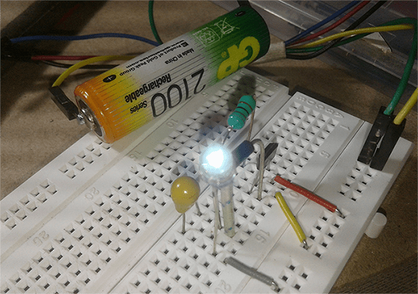
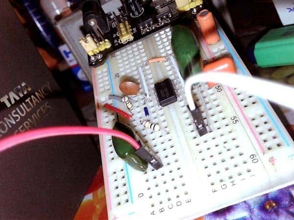
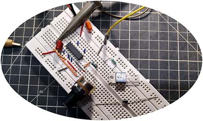
As usual, I tested my concept quickly by assembling the core circuit on a standard breadboard and used my oscilloscope for quick evaluation.
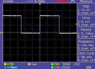
This is a casual waveform captured by the oscilloscope when it’s probed to Pin 4 of IC1:
And, this is what I got when hooked the scope to Pin 1 of IC1 (ac-coupled random probing):
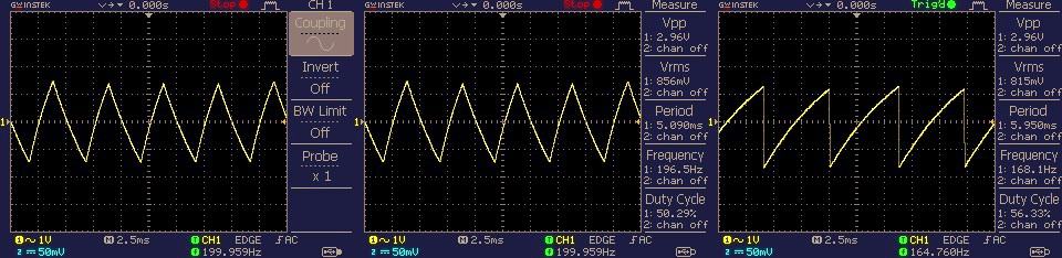
Then I completed the overall wiring and tested the working of my entire breadboard build successfully. Please note that the 100uF capacitor (C3) is the buffer/smoothing capacitor I had to add to the circuit at the end of the construct. It may not be absolutely essential depending on your power supply and cooling fan, but it is probably a good idea to include it for good measure. Moreover, setting the oscillator frequency as high as practical will minimize the audible fan noise.

Also note that every fan motors have a typical start voltage, and it’s observed that a duty cycle of under 35% would reduce the average voltage below my test fan’s start voltage. However, once the fan is spinning, we can utilise the PWM function to vary the fan speed from minimum to maximum in a nearly smooth manner.
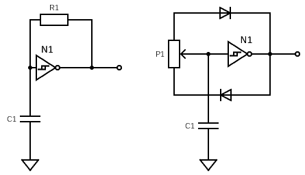
Now to a bit of useful theory! Actually, how does this oscillator circuit works?
In the below circuit, when N1 output is High, the capacitor C1 charges through resistor R1, and when C1 voltage reaches the positive trigger threshold, N1 output inverts & falls to Low. Now C1 discharges through R1, and when C1 voltage reaches the negative trigger threshold, N1 output inverts and rises to High. This process repeats to generate a 50% duty cycle square wave output.
By separating the charge & discharge paths with resistors and diodes, we can easily alter the duty cycle. Besides, replacing those resistors with a single potentiometer, we can then setup an adjustable (continuously variable) duty cycle astable multivibrator. Yes, you are good to go with just a single Logic NOT gate (https://www.electronics-tutorials.ws/logic/logic_4.html)!
Talking aboveboard, I have actually made two versions of this project – the first is the one presented here (prepared just to quickly learn how the circuit works on a breadboard). The other is a more practical automatic version with a proximity sensor and a homemade nifty wooden box. And, it has a stacked carbon filter consists of foam and activated carbon, which is ideal for absorbing toxins (https://www.amazon.com/Extractor-Replacement-Activated-Absorber-Xytronic/dp/B07D5SBPN8).
And that’s it. Watch this space often to see the sequel of this project!