Spider wrap is a type of security device used by many retailers. It’s simply a wired alarm that is attached to products to prevent theft. If the wire on the spider wrap is cut, the alarm sounds. In this post, you can see an extremely interesting do it yourself electronics project of a poor man’s spider wrap based on an Arduino microcontroller!
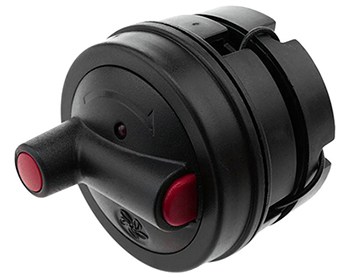
Spider Wrap & EAS
Spider wraps also known as wired alarm clips are broadly used in electronic article surveillance universe to protect pricey goods that are to be manipulated by the patrons.

According to Wikipedia, electronic article surveillance (EAS) is a technological method for preventing shoplifting from retail stores, pilferage of books from libraries, or removal of properties from office buildings. Special tags are fixed to merchandise or books. These tags are removed or deactivated by the clerks when the item is properly bought or checked out. At the exits of the store, a detection system sounds an alarm or otherwise alerts the retail staff when it senses active tags!
There are several major types of electronic article surveillance systems:
- Electro-Magnetic, also known as magneto-harmonic or Barkhausen effect
- Acousto-magnetic, also known as magnetostrictive
- Radio Frequency also is known as RF
- Microwave
- Video surveillance systems
- Concealed EAS Surveillance Systems
For more details, go to https://en.wikipedia.org/wiki/Electronic_article_surveillance
AM & RF EAS Systems
Although diverse electronic article surveillance systems exist, two types of EAS technologies dominate the retail business. Acousto Magnetic systems (AM) which operate on 58kHz and Radio Frequency systems operating on 8.2MHz. In each case, an EAS tag or label is attached to an item. The tag is then removed or deactivated so it will not trigger the detection system. If the tag is a reusable tag or so-called hard tag, a detacher is used to remove it when a customer purchases the item it is attached to. If a tag is a disposable tag, also called sticker tag, paper label, or DR label, it can be deactivated by swiping it over a deactivator pad.
Acousto Magnetic (AM) systems have the ability to protect exits up to 2.40 meters using disposable labels. The AM system employs a transmitter signal of 58kHz in pulses, which energizes a tag in the detection zone. When the pulse ends, the tag responds, emitting a single frequency signal. While the transmitter is switched off between pulses, the tag signal is detected by a receiver. And if the signal meets all the criteria, the alarm will sound. AM labels or tags are composed by two amorphous metal plates. An AM deactivator is used to deactivate or reactivate an AM labels.
Radio Frequency (RF) security tags/labels, usually attached to a product respond to a specific frequency transmitted by a pedestal at the entry/exit of a store, basically consists of a miniature electronic circuit and an antenna. The response from the label is then picked up by a receiver antenna. The receiver processes the label response signal and will trigger an alarm if the signal matches defined criteria. The distance between two pedestals can be up to 2 meters. Operating frequencies for RF systems range from 1.8 to 10MHz As different from hard tags, RF labels operate on 8.2 MHz, and this is also the most commonly used radio frequency.
Excerpts from a post found here https://www.eassourcing.com/how-eas-works
More technically, the key difference between the two is the frequency at which they operate, which is measured in Hertz. AM (Acousto Magnetic) systems operate at 58KHz, which means a signal is sent out in pulses or bursts between 50 and 90 times a second while RF (Radio Frequency) operates in a sweep at 8.2MHz.
Where to Learn More? Look here www.madehow.com/Volume-3/Antishoplifting-Tag.html
Although I’m here to inspire, support, and hopefully teach all of you, I don’t want to bore you by proving the whole theory – if you have doubts, Google it. Well, let’s move towards the do it yourself spider wrap project!
Poor man’s Spider Wrap
In order to build a little wire band security alarm, there seems no reason to go ahead with a brainy Arduino microcontroller as it might be redundant in many respects. Anyway, I still stick to my first idea — reckoning future expansions on the basic scheme.
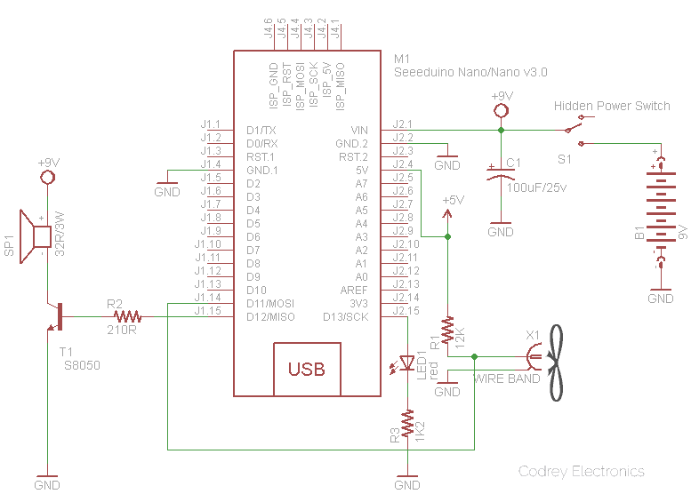
See the hardware setup diagram:
This is the Arduino Sketch:
/*
 * Poorman's Spider Wrap
 * Build Your Own Antishoplifting Device
 * Hardware: Seeeduino Nano/Arduino Nano v3/Arduino Uno r3
 * Arduino Sketch: v1.0
 * Author: T.K.Hareendran/08.2020
 * Note: Reading the entire article is an absolute must!
 */

#define alertLED 13 // Alert Lamp Output D13
#define sounderPin 12 // Alert Sounder Output D12
#define wireBand 11 // Wire Band Input D11

int state = 0;

void setup()
{
    pinMode(alertLED, OUTPUT);
    pinMode(sounderPin, OUTPUT);
    pinMode(wireBand, INPUT);
}
void loop()
{
    state = digitalRead(wireBand);
    digitalWrite(alertLED, state);
    if (state == 1)
    {
      for(int hz = 440; hz < 1000; hz++){ // Siren Generation
        tone(sounderPin, hz, 50);
        delay(5);
      }
      noTone(sounderPin);

      for(int hz = 1000; hz > 440; hz--){
        tone(sounderPin, hz, 50);
        delay(5);
      }
       noTone(sounderPin);
    }
    else{
      noTone(sounderPin);
    }
}
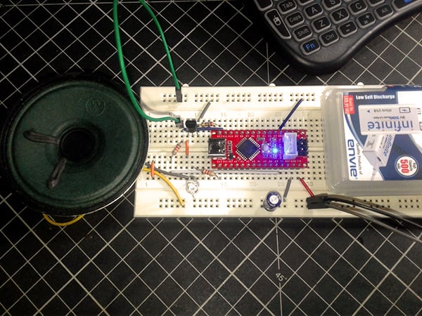
It is possible to run the entire assembly on a USB power supply connected to the Seeeduino Nano or Arduino Nano v3/Uno r3 board. However, the prospect of a power-hungry alert sounder heavily drawing power from the setup made me worry. Look, a standard loudspeaker with an impedance of 8Ω gobbles up a lot of current ~ 600mA maximum, and that beefy loading could overwhelm the modest resources of the current hardware setup. Therefore, I paused for thought and employed another 32Ω/3W small loudspeaker – driven by a 9VDC power source – as the alert sounder. From that moment the 9VDC power supply furnished by my good old 9V/500mAh USB (Li-ion) battery pack renders ample power necessary to keep the whole hardware assembly aright!
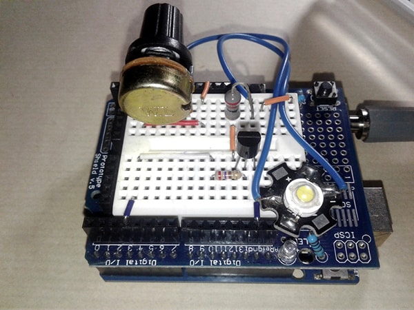
This is how my breadboarded spider wrap looks like in idle state (sorry for my terrible photographic skills):
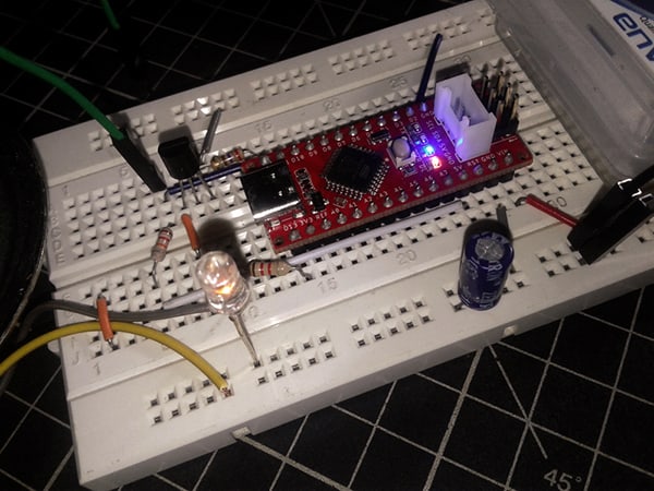
And, now you can see its active state i.e. with the broken wire band (green jumper wire):
Warning! Do not connect the loudspeaker directly to the microcontroller’s I/O pin. For a quick test you can attach a high-impedance (64Ω or so) headphones directly to ground and the concerned I/O pin, but to use a standard loudspeaker in this setup you should add a small amplification circuit wired between the I/O pin (D12) and the loudspeaker (SP1) as depicted in the schematic. By using the BJT (T1) you can extend the drive capability of your microcontroller (you are no longer restricted to devices under 40mA). Further, even though I tried a small but powerful loudspeaker lifted from a defunct bluetooth speaker, I strongly recommend a “piezo-speaker” as the sounder as it’s more suitable for this project. And then, you may try a 1.2KΩ resistor in lieu of the 210Ω resistor (R2).
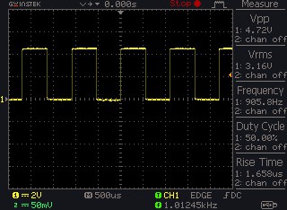
Following is a random screen capture while my DSO was probed to D12 of Seeeduino Nano!
That’s all for now. Note that this project is for basic demonstration only. There are many other things to consider, maybe the next one in this sequel will give you better build ideas you seek!