Hopefully this short post will give you some practical pointers for making your own LED spotlights that also includes a servo actuator. There are dozens of different ways to drive standard hobby servos, and here you’ll find a Raspberry Pi Pico-based project idea for a good start!
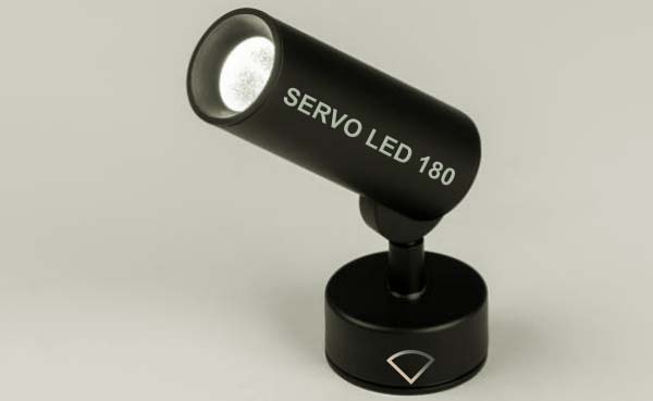
As you know, small robotic arms are widely used for small stage lighting or similar tasks. A servo motor that is part of the lighting fixture can move the light beam horizontally or vertically at a slow speed. And the brightness or color of the light beam changes accordingly.
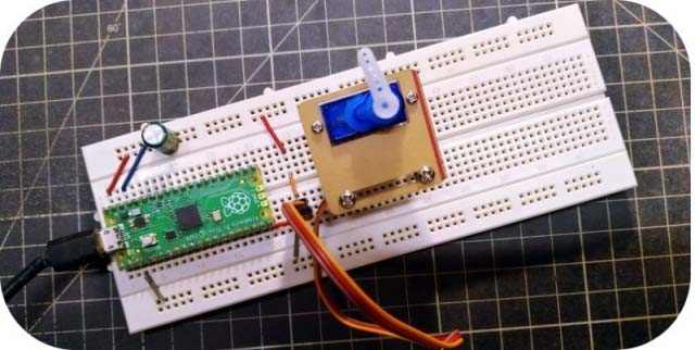
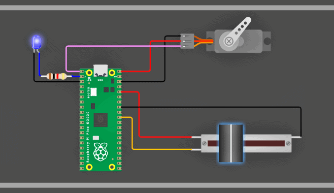
In its most basic form, my test setup comprises a Raspberry Pi Pico, a hobby servo, and a linear potentiometer. The potentiometer sets the analog voltage at the ADC input GP26 of the Raspberry Pi Pico and controls the hobby servo wired to Pico’s GP0. It controls the brightness level of the LED wired to Pico’s GP1 as well.
Below you can see the hardware setup diagram.
At this point, I have chosen the following key components. You’ll also notice that the setup is powered with a 5V/2A USB wall adapter. On my workbench, performance was as anticipated when some quick tests were performed (couldn’t take photos of it due to some unforeseen technical matters).
- Raspberry Pi Pico x1
- 10KΩ Slide Potentiometer (linear taper) x1
- Tower Pro SG90 9g Mini/Micro Servo x1
- 5mm Blue LED with 1KΩ ¼ W Resistor x1
For this project, I wrote a simple Arduino-style code for the Raspberry Pi Pico.
#include <Servo.h>

Servo PicoServo;

int ledpin = 1; //GP1
int potpin = 26; //GP26
int val = 0;

void setup()
{
  PicoServo.attach(0); //GP0
}

void loop() {
  val = analogRead(potpin);
  int LED = map(val, 0, 1024, 0, 255);
  int SERVO = map(val, 0, 1024, 0, 179);
  PicoServo.write(SERVO);
  analogWrite(ledpin, LED);
  delay(20);
}
This expansible code simply follows the potentiometer’s wiper to control the brightness of the LED and the servo sweep. That means, when the servo is counterclockwise, the LED dims or turns off. When the servo is clockwise, the LED is bright.
You need to have a rigorous read of this recent post (https://www.codrey.com/raspberry-pi/raspberry-pi-pico-arduino-ide/) to upload the above code to Pico from your Arduino IDE.
And, now it’s time for a WOKWi simulation. For that go through this link https://wokwi.com/projects/338798308914889299
As a concluding note, if you are connecting anything more than a small/low-current LED to the GP1 output, you should use an additional driver circuit to boost the voltage and/or current. This is because the GPIO pins are connected directly to the RP2040 chip at the heart of the Raspberry Pi Pico microcontroller board. These provide only a 3.3V logic-level output, and are not capable of supplying ample power.
For this reason, circuits based on logic-level power MOSFETs, similar to the one shown below, is often used for driving power LEDs.
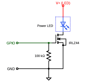
In this configuration, supply voltages (V+) higher than 3.3V may be used for the Power LED. Note that the IRLZ44 MOSFET has a maximum (VDS) voltage of 60V, and suitable for load currents of about 50A ().
As an aside, Fairchild’s FQP30N06L Power MOSFET has a low threshold voltage (2.5V max) and can handle 32A at 60V.
Thanks for reading! It is hoped that this little post has given you an idea of how to get started with using a Raspberry Pi Pico to drive hobby servos and solid-state lamps. If you need assistance choosing components that will suit your hobby-level Servo-LED projects, feel free to drop the query in the comments box below. I will be happy to assist you 🛠