A servo motor is a compact motor whose shaft turns to position something based on a control signal. The common servo motor consists of plastic housing that contains a small motor, control circuitry, and a few gears for torque. A servo motor can be used to position or adjust almost anything, for example, to steer a remote control vehicle. In this post, I will show you how to drive a regular servo with Raspberry Pi Pico!
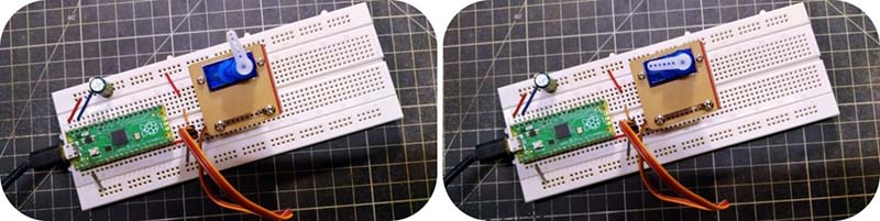
For this experiment, I’m using a Raspberry Pi Pico board and the quite common TowerPro SG-90 Micro Servo. Below you’ll find the hardware setup diagram.
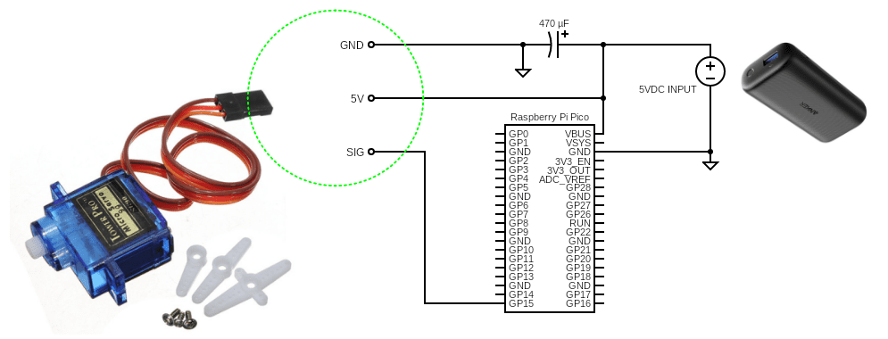
This simple setup can be powered by feeding a regulated 5VDC supply through Raspberry Pi Pico’s VBUS input, or you can connect a micro-USB power supply via Raspberry Pico’s onboard micro-USB connector (recommended). Anyway, it’s advisable to read this post beforehand https://www.raspberrypi-spy.co.uk/2021/01/pi-pico-pinout-and-power-pins/
The TowerPro SG90 Micro Servo is a powerful tiny and lightweight servo that can rotate approximately 180 degrees (90° in each direction). It comes with 3 servo horns (arms) and hardware. Its position “0” (1.5ms pulse) is middle, “90” (~2ms pulse) is all the way to the right, and “-90” (~1ms pulse) is all the way to the left. Whether +90° or – 90° is left or right will depend on how you mounted the servo!

As you already know, servo motor control of the shaft position comes from using a pulse width modulation (PWM) signal to turn the shaft clockwise (CW) or counterclockwise (CCW), depending on the pulse width of the signal. Typically, a pulse width of 1ms will rotate the shaft all the way to the left and a 2ms pulse will rotate the shaft all the way to the right. To position the shaft halfway (in the middle), a 1.5ms pulse typically works. And, you will need a 20ms period between each pulse.
Note: If you try to turn more than 180° it starts humming and vibrating and gets somewhat hot as the motor tries to turn more than the stoppers in the gear assembly allow.
Okay, let’s get into driving the SG90 micro servo motor using the Raspberry Pi Pico board. In this experiment, I’m using a simple “servo-sweep” MicroPython code to drive my servo motor. Below is the code for the servo sweep scheme.
import machine
import utime

servo = machine.PWM(machine.Pin(15))
servo.freq(50)

def interval_mapping(x, in_min, in_max, out_min, out_max):
    return (x - in_min) * (out_max - out_min) / (in_max - in_min) + out_min

def servo_write(pin,angle):
    pulse_width=interval_mapping(angle, 0, 180, 0.5,2.5)
    duty=int(interval_mapping(pulse_width, 0, 20, 0,65535))
    pin.duty_u16(duty)

while True:
    for angle in range(180):
        servo_write(servo,angle)
        utime.sleep_ms(20)
    for angle in range(180,-1,-1):
        servo_write(servo,angle)
        utime.sleep_ms(20)
When this program is running, you can see the servo horn starts sweeping back and forth from 0° to 180°.
From the datasheet, we see that the SG90 expects a frequency of 50Hz on the control line, and the position it moves to depends on the pulse width of the control signal.
Here we do not change the PWM pulse width, but we need to change the Duty Cycle.
Note that, Duty Cycle = Pulse width x Frequency.
So, given a 50Hz frequency, we can calculate the requisite duty cycle for any pulse width.
For example:
- We need a 1.5ms pulse to centre the servo, or a duty cycle 0.0015×50 = 0.075 =7.5%.
- Likewise, 1ms pulse (- 90 degrees) requires a duty cycle 0.001×50 = 5%.
- And 2ms pulse (+ 90 degrees) demands a duty cycle 0.002×50 = 10%.
Thus, in theory, the duty cycle range should be from 5% to 10% with the center at 7.5%.
- PWM & PPM – Further Reading http://www.endurance-rc.com/ppmtut.php
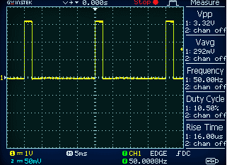
During my experiments, an oscilloscope was used to measure the PWM pulse width as it went through the program. Below you can see a random oscillogram.
The next thing to say is about the 5VDC power source. Sadly, most SG90 datasheets only help with the wiring and pulse width details. But we also need the real power consumption of the servo. After a thorough search, it’s found that the SG90 micro servo demands 220 ±50mA running current (no-load) and 650 ±80mA stall current (horn locked) at 5VDC. The idle current consumption is 6 ±10mA.
So, you might have to add a large capacitor (470uF/16V minimum) to the 5VDC (>1A) power supply rail because the servo can drain large amounts of current which may badly affect the Raspberry Pi Pico microcontroller. You can, if you prefer, power the servo from a battery pack rather than the micro-USB power supply. The important thing is to have the servo and microcontroller GND rails connected.
That’s all for now. Next up we will build another Raspberry Pi Pico + Servo project that we can use in the real world. I find myself desiring to use the same hardware things in different projects again and again but in various configurations!