This is an updated version of an old project that was published in EFY Magazine (print) 21 years ago! Now you can see that article here https://www.electronicsforu.com/electronics-projects/solidstate-signal-lamp
This time I’m using a minuscule microcontroller to modify the design concept. Below are the project details of that Arduino Pro Mini Beacon Light. I hope this solid-state beacon light is a beautiful alternative to the revolving mechanical signaling lamps used in emergency service vehicles. Okay, let’s start from its schematic!
![]() These are the key parts required for this project:
These are the key parts required for this project:
- 3V/8MHz Arduino Pro Mini x1
- 5mm Red LED x 4
- 4K7 Trimpot x 1
- 100Ω ¼W Resistor x4
- 2-Pin JST Connector x1
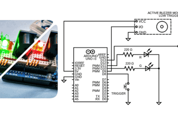
The schematic, as it seems, is extremely simple and straightforward. The 2-pin JST connector (CN1) is the DC input connector for the beacon light, which allows you to supply 4-12V DC voltage from any external power source.
Four I/Os (D8-D11) of the Pro Mini (M1) is used to drive four 5mm Red LEDs (LED1-LED4) through four 100Ω series resistors (R1-R4). Besides, a 4K7 trim pot (TM1) is connected between the Pro Mini’s VCC (3.3V) and GND (0V) pins, and its wiper (middle pin) is connected to the microcontroller’s first analog input (A0).
Needless to say, the code provided below must be uploaded to Pro Mini for this beacon light to work. Before I forget, you don’t have to stick to the default specific signaling pattern, simply change it as needed.
byte lamp_pin[] = {8, 9, 10, 11};
int lamp_delay;
int direction = 1;
int currentLED = 0;
unsigned long changeTime;
int speed_set = 0;
void setup() {
  for (int x = 0; x < 4; x++) {
    pinMode(lamp_pin[x], OUTPUT);
  }
  changeTime = millis();
}
void loop() {
  lamp_delay = analogRead(speed_set);
  if ((millis() - changeTime) > lamp_delay) {
    changeLED();
    changeTime = millis();
  }
}
void changeLED() {
  for (int x = 0; x < 4; x++) {
    digitalWrite(lamp_pin[x], LOW);
  }
  digitalWrite(lamp_pin[currentLED], HIGH);
  currentLED += direction;
  if (currentLED == 3) {
    direction = -1;
  }
  if (currentLED == 0) {
    direction = 1;
  }
}
This code is also transparently clear! See, it simply moves four LEDs consecutively in both directions, but at a speed specified by the trimpot TM1. The analog input A0 has a voltage level that corresponds to the wiper position of the trimpot and depends on the actual voltage level of VCC.
The 3.3V Pro Mini’s analog pins are able to read voltage levels up to 3.3V by a so-called analog-to-digital converter (ADC). As a result, the analog value will be available as digital values in the Arduino program. The digital values range from 0 (for 0V at analog pin) to 1023 (for 3.3V at analog pin).
If everything is wired correctly and the code has been transferred to the Pro Mini, the program starts to run and controls the LEDs as elaborated before.
I think you will agree that a circular LED circuit board with Pro Mini in the middle makes the entire build more compact. Anyway, below you’ll see a crude components layout concept.
![]()
Below is the inside view of a common Chinese LED Beacon Light (source of my inspiration).
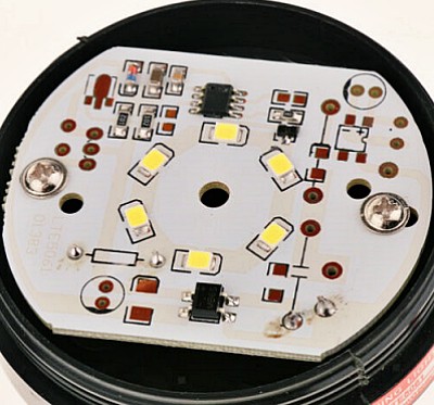
For the enclosure, you can buy a ready-made LED signal lamp housing online or make one with a 3D printer – not a big deal these days!
![]()
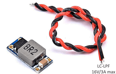
I often get asked which device should be used to combat noise in automotive power rails. The simplest answer is the Automotive Power Filter Module (see a sample below).
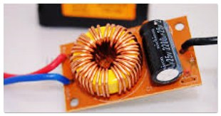
This Automotive Power Filter is basically an LC Filter which’s so simple and cheap to buy or make. Here’s how the L-C components are wired in this LC filter.
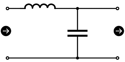
This is in fact the typical arrangement of a power supply low pass filter (LPF) built with an inductor and capacitor. It’s meant to prevent certain high-frequency AC components. If you need a basic refresher, LC filter refers to a circuit consisting of a combination of the inductor (L) and capacitor (C) to cut or pass specific frequency bands of an electric signal. The capacitor blocks DC current but allows AC more easily at higher frequencies. Conversely, the inductor allows DC current as they are, but AC less easily at higher frequencies. By combining these two components with opposite properties, noise can be cut and specific signals can be identified.
Take my word that the output voltage from a DC power source is a perfect horizontal line when observed on an oscilloscope in an ideal world. However, the real world is far from ideal and the output is never a perfect line – the power supply is susceptible to ripple and noise, especially in an automotive power supply system.
Since the value of the inductor and capacitor in an LC filter changes the resonant frequency, it’s pretty easy to suppress unwanted noise more effectively if you know the noise frequency. However, make sure the filter you are getting meets the voltage and current rating for your proposed application. Furthermore, to suppress high-frequency noise efficiently, you’ll need to pick a capacitor with low ESR and ESL values (I’ll explain more about this in another article).
As always, I made the prototype on a breadboard. Below you will find some casual snaps of it.
That’s all for today. I hope you enjoyed the post. As always, feel free to suggest any new topics in the comments. See you again soon!