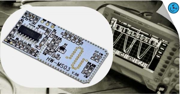
This is a quick revision of the cheap and popular motion sensor radar module RCWL-0516 (https://www.codrey.com/electronic-circuits/microwave-radar-motion-sensor-switch/).
The RCWL-0516 module would be a good choice for making motion sensing lamps and other devices, and it probably looks a lot easier than using a passive infrared (PIR) motion sensor!
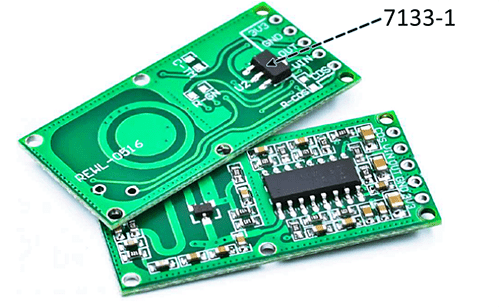
First off, note that today’s RCWL-0516 modules actually use the RCWL-9196 chip but appear to have identical functionality to those with the RCWL-0516 chip on them.
Specifications:
- Power: 4-28VDC @ <3mA
- Detection Range: ~5-9m
- Frequency: ~ 3.2GHz
- Transmitting Power: 20mW (typical)/30mW (maximum)
- Output Level: ~3.3V HIGH / <0.7 LOW
- Output Drive: ~30mA @ 3.3V
- Output Timing: ~2sec Retrigger with motion
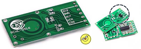
Pin Notations:
- 3V3: 3.3VDC Output
- GND: Ground (0V)
- OUT: Module Output (HIGH when triggered)
- VIN: DC Input (4-28V)
- CDS: External Photoresistor (LOW = Trigger Disable)
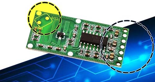
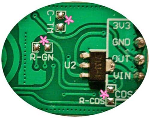
Solder Pads:
- C-TM: Solder pads for an optional SMD resistor to set the trigger (output pulse) cycle time. The default time is 2s
- R-GN: Solder pads for an optional SMD resistor to set the detection/gain range. The default detection range is 7m, adding a 1M resistor reduces it to 5m
- R-CDS: Solder pads for an optional SMD resistor (50-100KΩ) to set the detection sensitivity of the optional thru-hole photoresistor
The CDS thru-hole solder pads (left in the above image) are for mounting a photoresistor (CdS Cell) to disable the output trigger in daylight.
Compared with the traditional PIR motion detectors, this “microwave radar” motion detector module features penetrating detection capability. The component side of the module is the positive sensing face, the opposite is the negative sensing surface which is less effective. The positive sensing side should face the objects being detected, but do not obstruct it with anything metallic. The rear side should have a clearance of more than 1cm from any metal.
When triggered its trigger output pin will switch from (LOW) 0V to high (3.3V) for circa 2-3 seconds before returning to its idle LOW state. Note that the output pin remains in LOW state (regardless of the trigger status) if the voltage on the CDS pin is lower than 0.7V.
When recalling the experiences of my old trials (https://www.electroschematics.com/get-started-microwave-radar-motion-sensor/) moving a hand or an object rapidly in front of the RCWL-0516 module does not render much response. However, moving a hand slowly some distance away makes a much better response (the greater the distance the more cheerful the response seems to be). Thus, this amazing motion sensor module can be used in energy-saving and home/office automation projects. To give you an idea, electric lamps may switch on when a person enters the premise, stay on while the person moves around there, and switch off sometime after the person has left. Interesting?
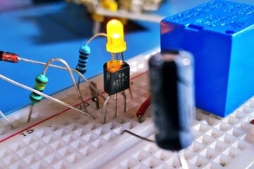
Since the module does not require any initial settings, it will work out of the box. For a standalone quick test, you can connect one regular 5mm LED between the GND and OUT pins of the module through a 1KΩ series resistor.
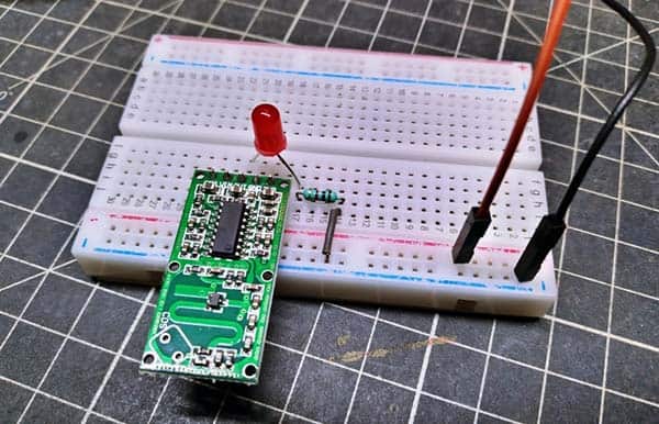
Once a movement has been detected the LED is fired by the module for a while. A 5VDC breadboard power supply can be used for a quick test.
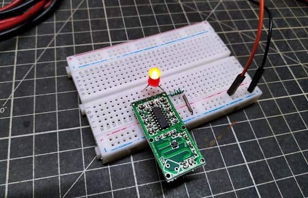
As it looks, the module has a “field of view” which means that better movement detection is achieved when an object is moved slowly in front of its positive sensing side. This can be tested by placing the motion detector upright on the edge of a desk and walk around it and to and from it during the quick test. Many online tutorials claim “360° radio wave field” but pretermits whether that field is in 3D or just planar. Surprisingly, I found that the back of the module sometimes gives a much better response than the front of the module facing the target. I need to learn a little more about this, but I’m not going into that right now!
After my quick tests, I was convinced that a standard LED could be connected at the output of the module (of course through a series resistor). I conducted the tests using “low current” red, green, and yellow LEDs. But at the moment I can’t guarantee how much current the output can provide happily!
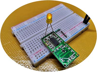
On another observation, plugging the module directly into a regular breadboard with a male header, the mass of metal strips caused unreliable operation (better, put the module on jumper wires, and keep it well away from the breadboard, or use a right-angle header).
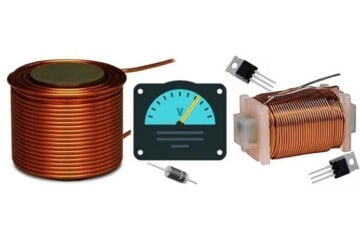
Further, the stabilized 3.3VDC output generated by the onboard LDO voltage regulator HT7133-1 (https://www.holtek.com/documents/10179/116711/HT71xx-1v250.pdf) can be used as a power source for some “tiny power” microcontrollers, but it doesn’t have ample juice to energize beefy things like power relays and lamps.
At this point, note that today’s RCWL-0516 modules come with a slightly different layout. Most significant is the back with the LDO voltage regulator Chip. That being said, the 3.3V output of the previous version is generated by the main chip itself, but in recent versions, you can see an independent 3.3V voltage regulator chip located at the bottom of the circuit board (perhaps, a clever inclusion).
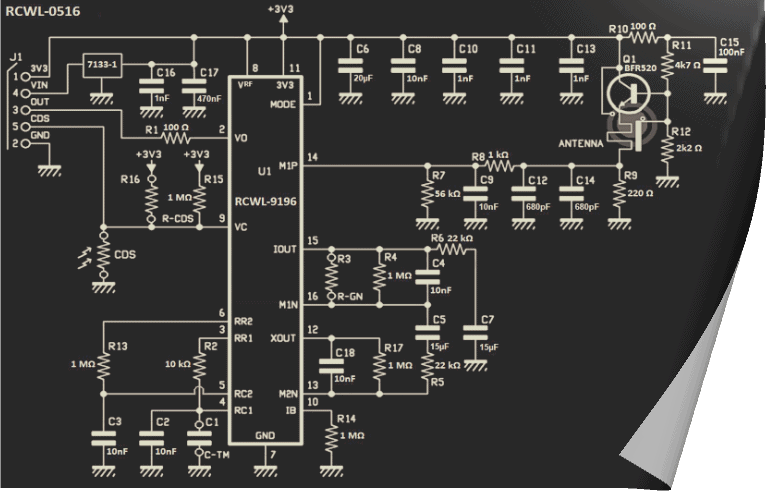
Below is the revised schematic of the RCWL-0516 module, borrowed from a seller’s site.
Here’re some basic things you need to pay attention to:
As already mentioned, you can stick an SMD capacitor on C-TM pads to tweak the repeat trigger time which’s circa 2-3 seconds by default (a high-value capacitor will make the trigger time longer). You can use capacitors ranging up to 1uF here.
Likewise, an SMD resistor on the R-GN pads will shorten the detection range (around 5-9 meters by default). However, do not use a resistor below 270KΩ here.
In addition, if you use the module to control a lamp, then it makes perfect sense to deactivate the trigger in daylight. For this, you can either solder a regular photoresistor to the CDS pads on the module or attach the photosensor to the CDS pin. But this alone is not enough, as you have to attach an SMD resistor to the R-CDS pads. Then, the value of the SMD resistor determines at which brightness the OUT pin becomes active again.
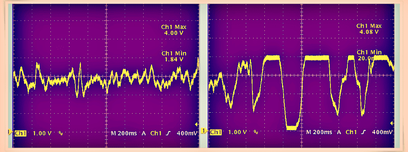
For those who are interested in further tinkering/hacking, an “analog” signal can be tapped from Pin 12 (XOUT) of the RCWL-9196 chip (see samples below).
Nothing more, I will try to post something about my random experiments with another microwave radar motion detector module soon. Stay Tuned…