The theory behind generating square wave is almost a trivial thing!
A square wave is a signal that changes between high and low state where the primary requirement is that the on-time (high state) and off-time (low state) are equal. Then the square wave signal has a 50% duty cycle. Simply put, a digital signal with exact same on and off time can be considered as a square wave.

Generating a square wave using an Arduino is as simple as turning on an I/O, wait for a certain amount time, turn off the I/O, wait for a certain amount of time and continue the cycle indefinitely. While there are so many ways to do this, using the following code is the first and simplest option.
void setup() {
  pinMode(12, OUTPUT);
}
void loop() {
  digitalWrite(12, LOW);
  digitalWrite(12, HIGH);
}
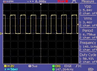
As you can see in the below oscillogram, the D12 I/O of Arduino Uno provides a 50% square wave output that has a frequency close to 150kHz!
Next is a revision of the above code which directly writes to PORTB thus avoids using the “digitalWrite()” function. Note that, writing directly to port is much faster than the traditional way!
void setup() {
  pinMode(12, OUTPUT);
}
void loop() {
  PORTB = B00000000;
  PORTB = B00010000;
}
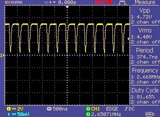
Now the frequency is around 2.7MHz! However, the square wave is not a symmetric one (duration of high time is greater than that of the low time).
On a side note, Arduino’s Atmel CPU (ATmega 328) runs at 16MHz, but that doesn’t mean that each instruction takes one clock cycle (62.5ns). Each instruction might take more than one clock cycle. In practice, there are some instructions that can often take one cycle or two cycles. So, in order to see what is going on, you need to go through the Atmel datasheet to find out how long each individual instruction takes.
Returning to our main theme, below is another bare minimum code needed to output a square wave through the digital I/O pin D9.
void setup() {
  pinMode(9, OUTPUT);
}
void loop() {
 analogWrite (9,128);
}
Now see the D9 output – it’s a 490Hz square wave with 50% duty cycle!

You can easily modify the above code by changing the second parameter of the “analogWrite” function to a different number in the range 0-255. At this moment, note that there is no parameter when using the analogWrite statement to specify the frequency of the square wave because the hardware that makes the signal always delivers the same frequency (but you can vary its duty cycle).
Arduino Uno has pulse width modulation (PWM) outputs on digital I/O pins 3, 5, 6, 9, 10 and 11. The frequency of PWM signal on pins 5 and 6 will be about 980Hz and on other pins will be 490Hz. On these pins the “analogWrite” function can be used to set the duty cycle of the pulse train that operates at a fixed (predefined) frequency (https://www.arduino.cc/reference/en/language/functions/analog-io/analogwrite/).
Next is a borrowed code to configure your Arduino Uno as a square wave generator that can be controlled through the serial port.
unsigned int freq = 0;
int sqwPin = 13;
void setup() {
  Serial.begin(9600); // Serial Port Baud = 9600 8,N,1
}
void loop() {
  while (Serial.available() > 0) {

    char tmpChar = Serial.read();
    if (isDigit(tmpChar)) {
      freq = (freq * 10 ) + tmpChar - '0';
    }
    if (tmpChar == '\n' || tmpChar == '\r') {
      if (freq > 0) {
        Serial.print(freq);
        Serial.println(" Hz SQW OUT OK");
        tone(sqwPin, freq);
      }
      freq = 0;
    }
  }
}
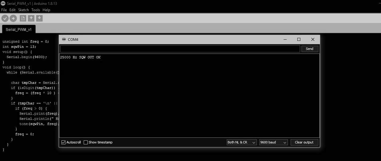
Using this setup is pretty simple. Just enter the needed frequency (in Hz) through your Arduino’s Serial Monitor to get a 50% square wave signal through the D13 I/O pin of your Arduino Uno. That’s all!
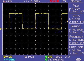
I monitored D13 pin with my oscilloscope. So, below you can see the 25kHz square wave output. Sweet!
At this point, keep note that the above code generates a square wave of the specified frequency (and 50% duty cycle) on the D13 pin. In practice, you can set the frequency from 50Hz to 50kHz, slightly lower and higher than that is permissible, though.
In closing
Considering my other posts, this may sound weird, but it’s intentional. Think of it as a quick refresher post, as soon as you can see some advanced pulse generator projects here. My plan (until now) is to use some odd analog and digital electronics techniques to design them.
Nice code, wish to know if it is possible to implement the choice of LOW and HIGH btween the cycle ?
Mario: Thanks! It seems possible, but I have not tried it yet, because I’m busy with some other urgent projects.
I hope this post helps you get proceed with your own code https://www.digikey.in/en/maker/projects/a-simple-square-wave-function-generator-with-an-arduino/6d08a053484c4a909f15eced6c3fe433 Good Luck!
Hello. Thanks for this. I have one question. If I tweak the output signal with a voltage booster and a MOFSET, would signal type change? I want 25V square wave at 100Hz-1kHz
@theirishman: Simply you can use the square wave to drive the Gate of a mosfet. Then connect positive rail of the 25VDC power supply to the Drain terminal of the mosfet through the proposed load (Source terminal of the mosfet must be grounded).
Of course this crude idea needs many refinements, which I will post in detail later. Thanks!