The first radio transmitters of the early 1900s were known as spark-gap transmitters. Spark-gap transmitters were broadly used on board ships where they provided the first means of communication to shore-based stations. As the name indicates spark-gap transmitters used a spark generated across a spark-gap in the transmitter.
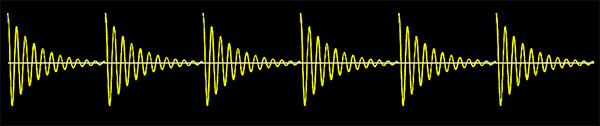
Wireless telegraphy began with spark gap transmitters in the 1890s. The spark gap transmitter is a simple device that produces repetitive radio-frequency (RF) pulses of significant power. The transmitter’s signal was a string of damped waves which repeated at an audio rate, and in a receiver sounded like a musical tone or buzz.
If you’re interested in reading more about wireless telegraphy in the late 19th and early 20th century, you can start with this Wikipedia article https://en.wikipedia.org/wiki/Spark-gap_transmitter
Now just dust your old school electronics textbooks to revise the interesting topic – electromagnetic induction. Most electronics devices generate electromagnetic noise. A small fraction of these electromagnetic emissions occur at frequencies that we could perceive if we could sense electromagnetism, but luckily, we can’t. However, an appropriate inductor can detect the EMF (electromagnetic field. The inductor will produce a voltage proportional to the fluctuating electromagnetic fields that cross it, and allow us to get them.
Spark Transmitter & Receiver Demo Project
First off, before the bushwalking, simply note that the focus of this post is actually on the construction of a very crude spark receiver, which can hopefully shed little light on the secrets of electromagnetic induction.
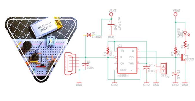
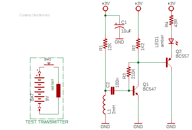
Below you can see the simplest schematic of a do it yourself spark receiver (forget the inset for a while). It’s very crude but good enough for a funny demonstration and/or to convince yourself that you too can build a spark communication system!
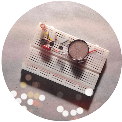
At first, assemble the spark receiver electronics on a piece of the perforated circuit board, and keep a CR2032 lithium coin cell (3V) handy to power it up later. As usual, I wired it on my mini breadboard but do not follow that dirty practice because it’s suitable for a stabile workbench experiment and nothing more.
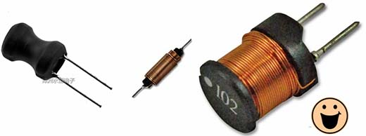
The circuit diagram shows a ‘tricky’ small-signal amplifier wired round two common transistors BC547 & BC557 (T1 & T2). The core component is a 2mH radial inductor (L1) connected to the amplifier. A common 5mm amber LED (LED1) is used at the output of the amplifier for a sensible visual signal indication. Note that you can replace the LED portion with a tiny loudspeaker or earphone (8-16Ω) to hear a crack in lieu of the twinkle when the inductor captured a transmitted spark/signal. The receiver works up to a distance of 10-20mm or so only. Not impressive, but bear in mind that this is a crude (and cheap) build for casual demos.
Honestly, this design needs minor refinements, too. I’d like to point out again that my primitive spark receiver can’t offer a long reception range due to certain circuit limitations. Anyway, the basic design is highly adaptable so you can experiment with various axial/radial inductors (minimum 1mH).
Likewise, the first 12K resistor (R1) is certainly not substantial in this particular tryout, but I set it there as I wanted to try some other ‘transducers’ instead of the common inductor. Maybe I’ll try that someday.
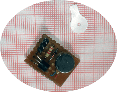
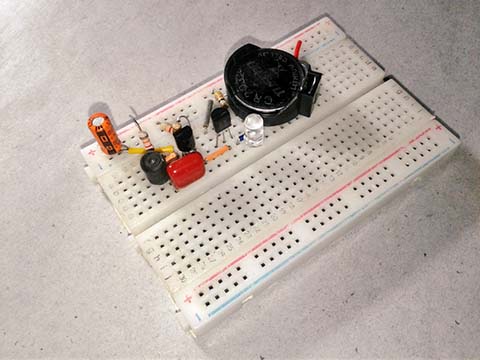
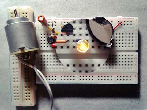
And now the associated spark transmitter also to be built for the quick test. The simplest method is to use an inductor (1mH -10mH) as shown in the inset of the schematic given before. In practice, the ‘sender’ doesn’t have to be an inductor, a common dc toy car motor is also possible. You only need to use a battery and a push-button switch in addition. In this idea, you’ve a crude spark transmitter – when you press the push button, the spark is transmitted, and there’s a response from the spark receiver if it’s within the loop. Here’s an image of the electronics in action, with the LED distinctly visible.
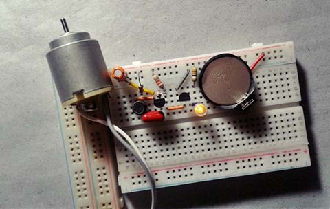
Two more snaps from my workbench:
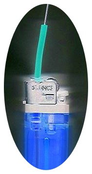
Moreover, it’s worth noting that you can build a spark transmitter using one empty disposable cigarette lighter with a piezo spark mechanism. Simply solder a short piece of stiff wire on the gas nozzle of the empty lighter as its antenna. And then, press the lighter’s fire button to briefly radiate electromagnetic energy. Recall, an electrical spark generates high frequencies!
So how well does it get out?
The project looks straight forward to get going, finding suitable inductors take some experimentation, though. Notably, the spark receiver only works when held close to the spark transmitter/source, often this is an advantage as it’s able to pick out individual waves in the electromagnetic sea. If you’re looking for a longer range and less selectivity system, you may need to do revise this rudimentary design idea. There’re umpteen ways to improve this idea. Similar devices are habitually finicky to build but are pretty cool once you get them working. Good luck!
At last, this’s just a quick demonstration, but I might make it more powerful in the future with the help of another clever idea acquired more recently. If you have any comments, questions, or corrections, please let me know. Thanks, and until the next adventure!
- For quick learning: http://www.awasa.org.za/articles/103-spark-transmitters
- A historic plug-in: Picture of the first German ship fitted with wireless (Marconi-System). On March 7, 1900, the German passenger liner SS Kaiser Wilhelm der Grosse becomes the first ship to send wireless telegraphy signals to shore!