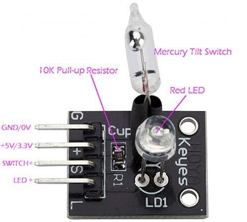
What is a Magic Cup Light Module you may be asking yourself? Well it’s an inexpensive Chinese module comprises a small mercury tilt switch and a light emitting diode. In this article, I’m going to show how to build funny electronics projects with the magic cup light modules.
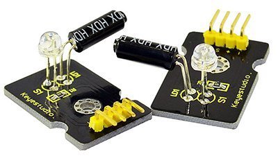
Brushing off the fancy name, we can see that the module is nothing but a crude switch and light module designed for 5V or 3.3V DC operation. As shown in the below schematic (drawn by me), the one and only extra component in the module is a 10K pull-up resistor.
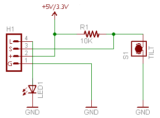
The mercury switch fitted in the module can be used to detect the tilt of something with respect to gravity. Notice that the mercury is encased in glass, with electrical connections going inside the encasing. Typically there is either air, an inert gas, or a vacuum inside. The mercury blob inside the glass tube is an excellent electrical conductor offers long operating life usually many decades.

So when the mercury is tilted on one end, it connects the “S” pin of the module to GND, giving a logic low (L) signal. And when tilted the other way, it connects to VCC through the 10K pull-up resistor, giving a logic high (H) signal. Mercury (Hg) is poisonous – Be careful at all times!
I assume this pretty odd module is intended to seat at the bottom of a cup as it lights up when the cup is tilted. I had seen them, but only bought a pair during the Xmas season.
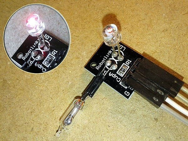
The module does not really need a microcontroller as it can work happily with a 5VDC power supply alone. See, at first I bridged the “S” and “L” connections together and powered up the module with 5VDC input. And then I tilted the module gently to switch the LED on and off – Yes, my idea worked well as awaited!
Another way of using the module is to add a 555 IC-based control circuit as pointed in the next schematic.
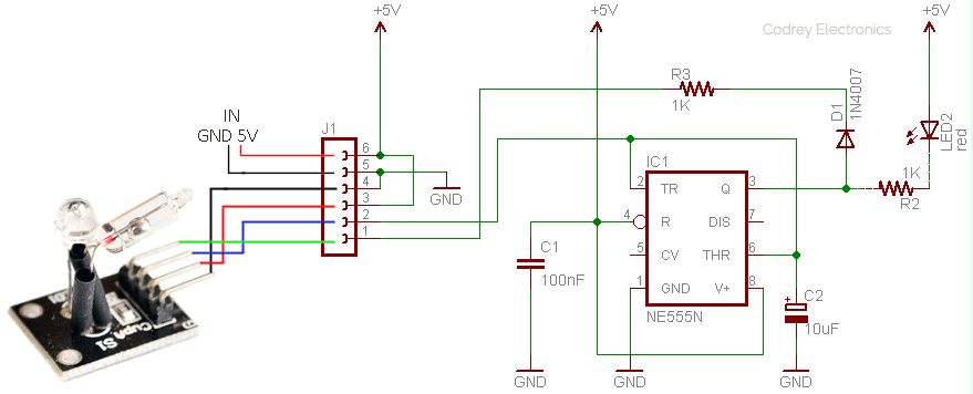
Here, the mercury tilt switch will ‘trigger’ the circuit to provide an output to switch a pair of LEDs – one already mounted on the magic cup light module, and an additional one wired externally with the control circuitry. The electrolytic capacitor (10uF-100uF) in the control circuit is included intentionally to introduce a little delay between the transitions.
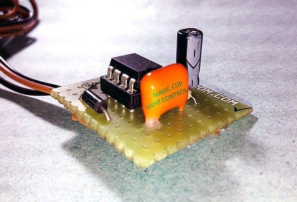
This is the photograph of my 555 IC based control circuit wired on a flake of FR4 prototyping circuit board. Looks good?
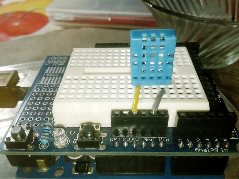
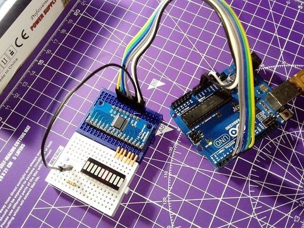
Anyway, since both the mercury tilt switch and the lamp are available singly (ofcourse sharing a common ground rail) I prepared a crude Arduino sketch that allows the execution to be tweaked, or tried in a much-advanced hobby project. See that get-go code below.
int brightness; //Brightness of the LED

void setup() {
  pinMode(9, OUTPUT); //LED (L) of the Magic Cup Light module to D9 via a 470Ω resistor
  pinMode(8, INPUT_PULLUP); //Tilt Switch (S) of the Magic Cup Light module to D8
}

void loop() {
  brightness = constrain(brightness, 0, 255); //Constrain brightness between 0 and 255

  analogWrite(9, brightness); //Write 'brightness' to the LED
  delay(10); //Pause at each brightness level

  if (digitalRead(8) == LOW) { //If tilted
    brightness = brightness + 1;  //Increase the value of 'brightness' by 1
  }

  else { //otherwise (if reversed)
    brightness = brightness - 1;//Decrease brightness by 1
  }
}
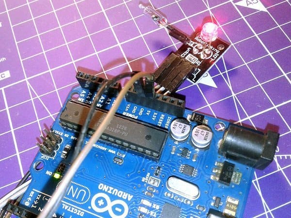
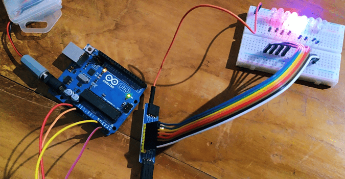
As usual, you can copy-paste and upload the above experimental sketch to your Arduino Uno board. Thereafter, slowly move the magic cup light module sideways to see the magic! Perhaps, you can find a better Arduino magic cup light module code here https://keyestudio.com/-p0382.html.
I admit, the magic cup light module covered here is in fact a piece of mirthful electronics, and only a standard mercury tilt switch is required to do the tilt detection job well. But look, I purchased a couplet of these modules for less than the price of a single 6mm mercury tilt switch – not a bad choice, indeed!
Further, not to impart nefarious ideas, but seemingly mercury tilt sensor were used in vehicle bombs as acceleration would trigger them. You didn’t get anything about that from me but keep note, a mercury tilt switch, for example, can be configured as a warning signal generator in a hill-climbing robot because the mercury switch could give an alert to the robot’s brain when it attains a certain angle, or when it’s getting up to a level that’s too steep in which case it will overturn.
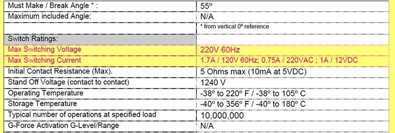
You may be wondering, why use a ‘dangerous’ mercury tilt switch when you can use a safe roll-ball tilt switch (https://www.codrey.com/electronic-circuits/universal-tilt-sensor/). Did you know? One significant advantage of the mercury switch is that it can handle very high voltages and currents. If you want, you can have it directly control a AC or DC load or some other high powered device directly. See the below image which is actually a snippet from the datasheet of T08-2010 – T08 series mercury tilt switch published by American Electronic Components, Inc. (http://www.aecsensors.com).
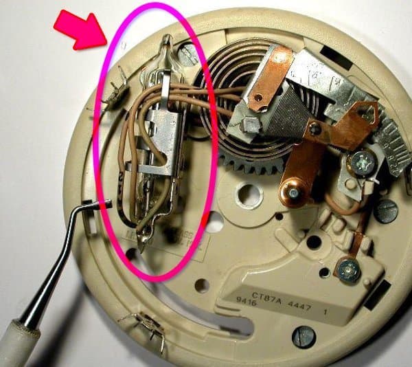
That’s why mercury tilt-switches (also called as mercury tip over switches) are broadly used in mechanical thermostats (see below image).
Finally, if you ended up using the magic cup light module to do something cool, please leave a comment below. Thanks!