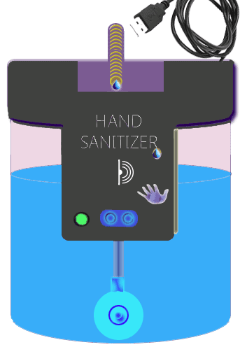
This article describes how you can build an easy to make automatic, touch-free, hand sanitizer dispenser at home. My design idea introduced here transforms a couple of readily available and ridiculously cheap discrete electronics parts into a portable hand sanitizer device you can put into service everywhere.
To duplicate my hand sanitizer project, you’ll need the following key components:
- TCRT5000 Reflective Sensor
- Micro Submersible DC Water Pump
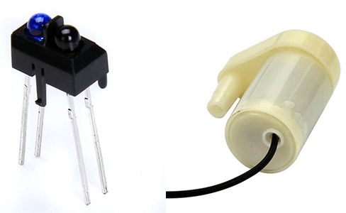
The TCRT5000 is an omnipresent little reflective sensor which includes a 950nm infrared light-emitting diode and phototransistor in a leaded package that blocks visible light with a peak operating distance of 2.5mm. The micro submersible water pump is actually rated for 6VDC operation but we can run almost all water pumps in this series smoothly through a 5V/500mA DC power supply.
The first step is to see the ultra-simple schematic and get familiar with how I intended it to work.
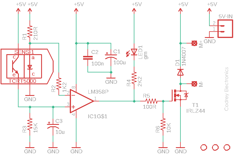
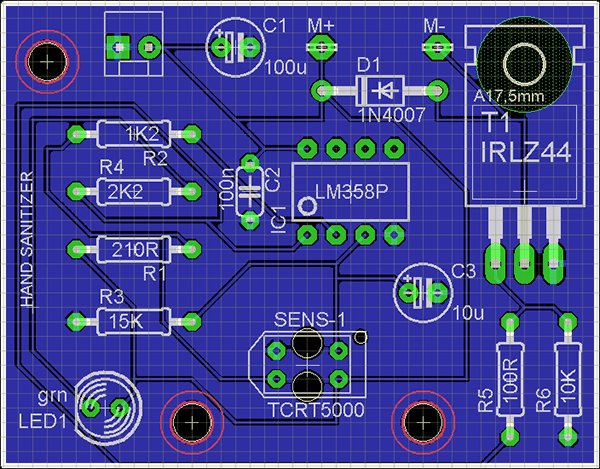
In addition to the key components pointed out before, you can see two more ‘big’ components in the given schematic. That’s quite usual – the LM358 dual op-amp (IC1) is wired as a comparator, and the IRLZ44 logic level power MOSFET is used as an electronic switch to control the water pump motor. The Resistor R1 limits the operating current of the infrared emitter inside the TCRT5000 (SENS-1) while resistor R3 works as a ‘load resistor’ for the phototransistor part of TCRT5000. The capacitor C3 is added intentionally to do a little stabilization, not very essential though. Likewise, resistor R4 limits the operating current of the standby indicator (LED1), and the remaining resistors R5-R6 are gate resistors of the IRLZ44 power MOSFET (T1). Further, the 1N4007 diode (D1) wired in antiparallel with the motor terminals is used to shunt the back-EMF spike, and capacitors C1-C2 are buffer/decoupling capacitors for LM358. Now note that the infrared emitter part of the reflective sensor also delivers a crude reference voltage (circa 1.2V) to the inverting input (Pin 2) of the op-amp through resistor R2.
This just about completes the quick description of the circuit. The circuit has been designed to allow acceptable operation from a stock USB travel charger or a USB power bank (the best way to do it).
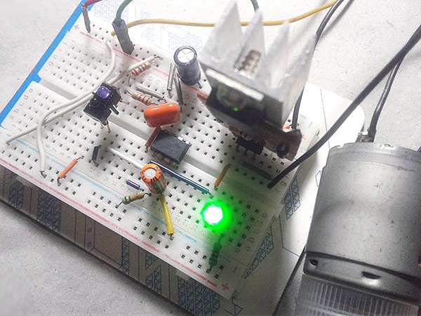
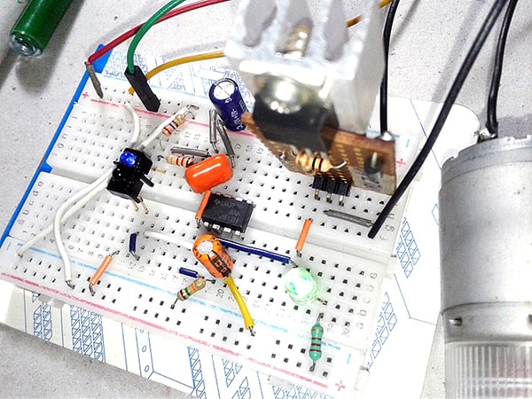
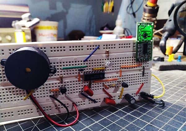
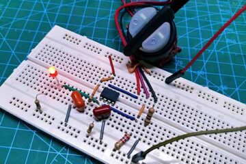
What else? The components, of course, and the actual construction but that should not present problems as only through-hole components are involved and a small perforated circuit board is enough. Instead of a IRLZ44 for T1 you could also use a IRL540 or something similar. Actually the MOSFET doesn’t need a heatsink in this project. Anyway, a small heat sink is good to keep the MOSFET cool especially if you’re in a plan to try another power-hungry water pump or a serious solenoid valve. See my rapid prototyping on a mini breadboard:
Once the board has been populated, fit the entire electronics in a modified mason jar (see the reference artwork below). The reflective sensor and the status indicator should, of course, be mounted incisively on the front face where they can be seen. The exact placement of the water pump inside the jar is not that critical—there’s a large margin to play with. Obviously, for the enclosure you can use a 3D printed one, the big mason jar is just an alternative!
Unfortunately, I can’t take the advantage of a readymade PCB, although almost all of a single-sided demo PCB’s layout has been completed before many weeks (see next image to get a glimpse of the art). I know, I need to keep my order alive until the China fab house restarts their PCB shipping service to India as before (the COVID-19 side effect). To support the hobbyists and to simplify the circuit board design, link of the Gerber files may be posted here after that. By the way, if you are designing a PCB yourself, pay special attention to power supply and motor track widths – large enough to cope with the actual drive current requirements (don’t follow me)!
Analog Supplement
Before you begin, some very important information needs to be highlighted, and for that, read this postscript. The TCRT5000 reflective sensor is essentially composed of an infrared light-emitting diode and a phototransistor responsible for filtering natural light. The amount of light reflected might depend on many aspects, mainly with the distance to the surface and the color of the surface. And, when using in sunny outdoors there’s a tenuous chance of malfunction because of the infrared components in the sunlight.
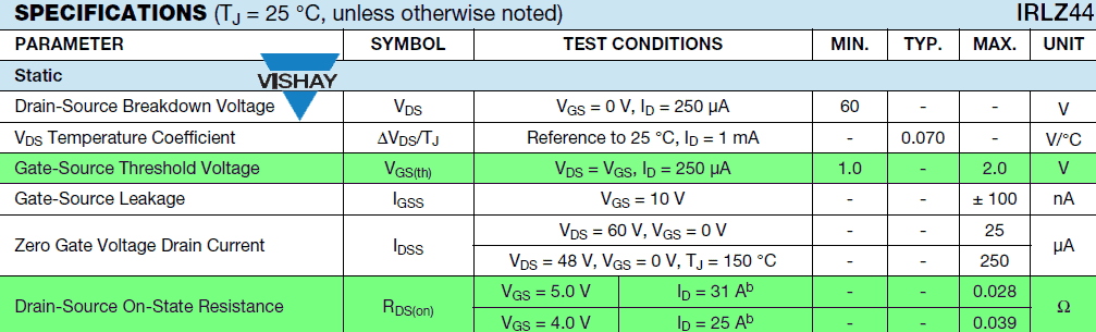
In the standby state, the voltage at the non-inverting input (pin 3) of LM358 is not large enough to consider but in case of a hand proximity detection (circa 30 mm detection range), it raises well above the 1.2V reference (Pin 2). This gives around 3.4V at the output (Pin 3) of LM358. A standard MOSFET is designed to pass the maximum current at gate voltages of around 10V and that is beyond what the LM358 can deliver here. The IRLZ44 (not IRFZ44) is a logic level MOSFET designed to turn on fully from the logic level of a microprocessor, so it’s used here as the water pump driver.
Whether a MOSFET is a standard one or a logic one becomes clear from its datasheet – a logic-level MOSFET will have Rds(on) specified for Vgs=5V or 4V. If its only specified for Vgs=10V, its certainly not a logic level type MOSFET. The next key look at the datasheets is the gate threshold voltage. Note down that this is not the gate voltage to turn the MOSFET on, its just the gate voltage at which the MOSFET switches fully off. If the gate threshold voltage VGS(th) is given as 2.4V range, it cannot be a logic level MOSFET as it is roughly 1V to 2V for a logic-level MOSFET.
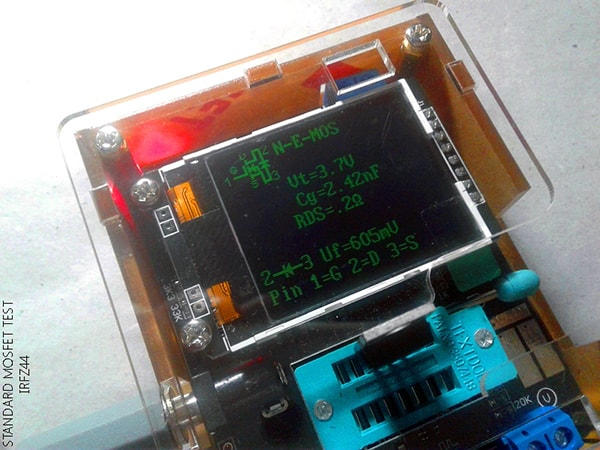
See the difference! This is the quick test report of a standard MOSFET, the IRFZ44.
Finally, it’s been noted nowadays that even simple electronic designs are getting increasingly complex in design and have a regretful tendency to attract microprocessors for no apparent reason. This is a zero-microcontroller fun project, cheap and unpretentious. Nevertheless, the performance of my ‘analog’ prototype is respectable. The hand proximity detection circuitry gives no grounds for complaint. The field of electronics has enormous potential to fascinate creative minds and it is not always necessary to splash the cash on expensive commodities. This project is an example of what can be achieved with very little outlay. So give it a good try!
Nice project.
1. Why not IRFZ44N ?
2. Does this work under sunlight ? I tried with a IR Proximity sensor and in broad daylight – it could not react very well. It was erratic. Was wondering how this sensor performs in ambient light.
Shashi Kiran: Thanks!
1. Why not IRZ44N? Read 3rd para of the session “Analog Supplement”
2. Does this work under sunlight ? Read 1st para of the session “Analog Supplement”
Further,for better outdoor operation, you may try changing the values of R1 and R3 to some extent. Or opt for a sensor module with “modulated” IR sender and receiver. I’ll come up with such a project, soon!