This time I’m going to show you how to build an inexpensive yet very useful generic 2A USB car charger for smartphones and tablets using off-the-shelf parts. What you can see here is a simplest do it yourself project of a cigar lighter port USB charger centered on a quite popular DC-DC buck (step down) converter module. The “6-24V input to 5V USB 2A Car USB module” as named by most online sellers is a clever and safe design centered on the high-efficiency, high-frequency, 3A,24V,500KHz synchronous step-down converter chip MP2315, introduced by Monolithic Power Solutions (www.MonolithicPower.com).
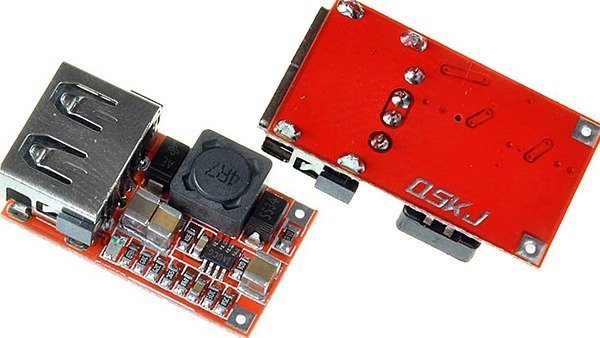
The module I got from Amazon badged “QSKJ” looks like an exact replica of the well-known “Ailavi”” module. Since the little module comes with almost all components pre-soldered, getting off the ground is very easy. All you needed is a handful of low-cost accessories to complete the entire build. Before the actual build, now let’s look at the module and see how it’s designed by the unknown Chinese design engineer!
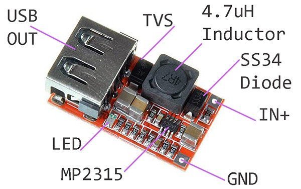
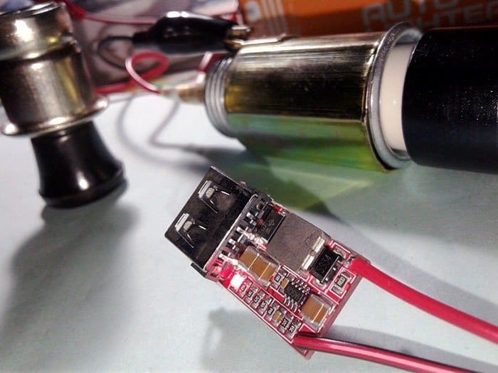
The workhorse is certainly the MP2315 (AGCG) switching regulator. While the MP2315 chip can cater up to 3A, it’s only considered safe for up to 2A continuous before the heat becomes a serious issue, but that 2A @ 5V DC output seems to be enough for most common smartphone/tablet USB car charger applications. Rather unsurprisingly, the module also has a reverse input polarity protection diode (ss34), and a transient voltage suppressor (TVS) added deliberately for output load protection. The unidirectional TVS diode with top marking “AE” reveals that its minimum breakdown voltage is 6.40 (7.07 maximum) because the 2-pin device type appears to be the SMAJ5.0A surface mount transient voltage suppressor from Vishay (www.vishay.com).
If you examine the module closely and compare it with the stock schematic from MP2315 official datasheet, you can see that there’s a bunch of extra resistors soldered on the PCB. Quite simply the inclusion supports both Android and Apple device charging as the trick helps to imitate a native charger. A native charger for smartphone/tablet often have a special voltage signature on USB data lines (D- & D+) to let the connected device identify the charger and figure out the maximum allowable charging current it can ingest from the power supply source (I’ll elaborate this afterwards).
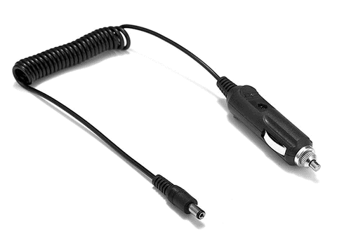
Okay, let’s build it. The construction is pretty simple because it needs just a 2-wire soldering work. First of all buy/prepare one car cigar lighter power plug with a standard DC plug (male) at its end (see next figure), and then solder a standard 2-wire DC socket (female) cable at the input pads of the MP2315 module (pay close attention to the +/- input connections).
Finally, put the MP2315 module inside a small USB project enclosure (see below). Done!

Lab Evaluation
Since the project is prepared to power/charge USB devices, the first test was to check the output voltage Since it’s USB, the output voltage supposed to be is 5V (+/- 5%), according to specifications. During evaluation, the observed no-load output was 5.10V which dropped to 5.06V under 1A load (happily in the limits of USB specifications). Coming to the efficiency test report, the observed efficacy while it’s tested with a 1A output load marked 87%, while it’s close to 84% with a 2.1A load. As stated before, the USB charger module has its own special way of signaling on the USB data lines. Here’s the actual measurements of the USB data line voltages:
| USB D- | 2.7V |
|---|---|
| USB D+ | 2.7V |
It’s worthy to note down that the most common USB Dedicated Charging Port (DCP) should have the D+ and D- data lines shorted (USB fast charge/1A) with a maximum series impedance of 200Ω, or just simply shorted together (0Ω). Samsung devices usually require 1.2V voltage on both D+ and D- data lines (Samsung fast/1A or 1.5A). Floating (un-connected) data lines seem to be universally interpreted as slow charge (500mA). However, this module’s configuration (2.7V on both D+ and D-) sets the default USB charge rate of the module to 2400mA (12W USB Charger)!
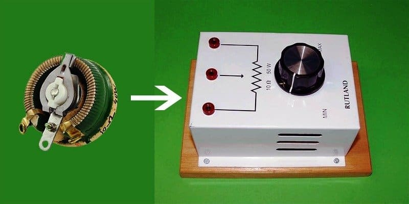
For the rough in-lab USB load test, you can connect one standard 10Ω /50W wire-wound variable resistor across the USB output (5V and GND) of the USB car charger. Then vary the resistance value to measure the available output voltage at different output loads. For example, dial 10Ω value for 500mA (2.5W), 5Ω value for 1000mA (5W), and 2.1Ω value for 2400mA (12W), and check if there’s a noticeable drift in the 5V output.
Finally, one casual snap from my workbench taken while I was testing the experimental setup with a car cigar lighter power socket (powered by an automobile battery):
Interested makers can buy the USB module used in this project from Amazon India. Here is one unbiased (no affiliation) link – https://www.amazon.in/Absolute-Native-Electronics-Ailavi-Converter/dp/B00XPZ7I4I