Even though I have a large collection of TP4056 modules for charging lithium-ion cells, I recently found a pretty small charger module – TP5100 – capable of charging a single lithium-ion cell or 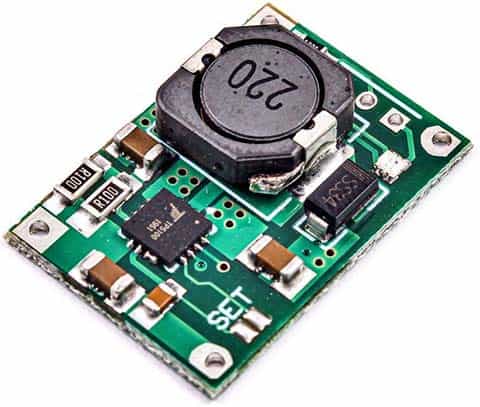 two lithium-ion cells wired in series at a time. After that, I quickly decided to build a 2S Li-ion battery charger with that inexpensive module. Not to mention, yet another successful build attempt!
However, this article is not about that project, but just my quick teardown notes. Well, let’s take our hammers to break its inside electronics.
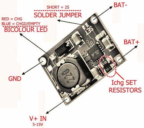
TP5100 1S and 2S Lithium Battery Charger Module
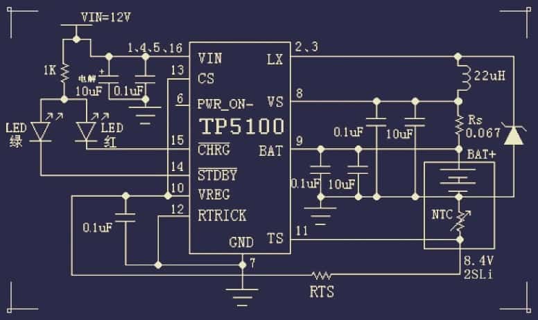
Needless to say, the main part of the module is the TP5100 chip from Top Power ASIC (https://voltiq.ru/datasheets/TP5100-datashhet.pdf). According to its datasheet, TP5100 is a step-down switching double 8.4V / 4.2V single lithium battery charge management chip with built-in input overcurrent protection, under-voltage protection, over-temperature protection, short circuit protection, battery temperature monitoring, and reverse battery protection. This is the official (Chinese) schematic of the TP5100 module:
Unfortunately, the available (machine-translated) technical information on this module is ill-defined (it’s regular, we all know that). See original Chinese datasheet https://grobotronics.com/images/companies/1/datasheets/20130410110217263.pdf
Anyway, here is a list of its key specifications obtained from a seller abroad:
- Dual-cell 8.4V/Single-cell 4.2V
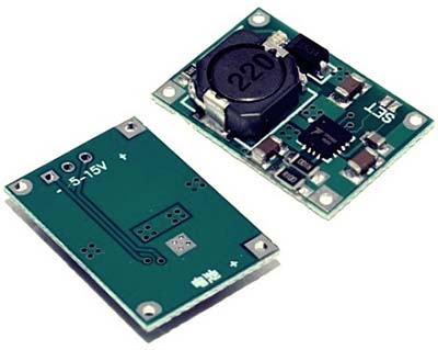
- Input voltage: 5V-15V DC
- Switching frequency: 400kHz
- Red LED: Charging indicator
- Blue LED: Full charge/ No battery indicator
- Both Red/Blue LED off: VIN very low/High-temperature shutdown
- No need for external anti-backflow Schottky diode
- Onboard solder jumper to set 1S/2S mode
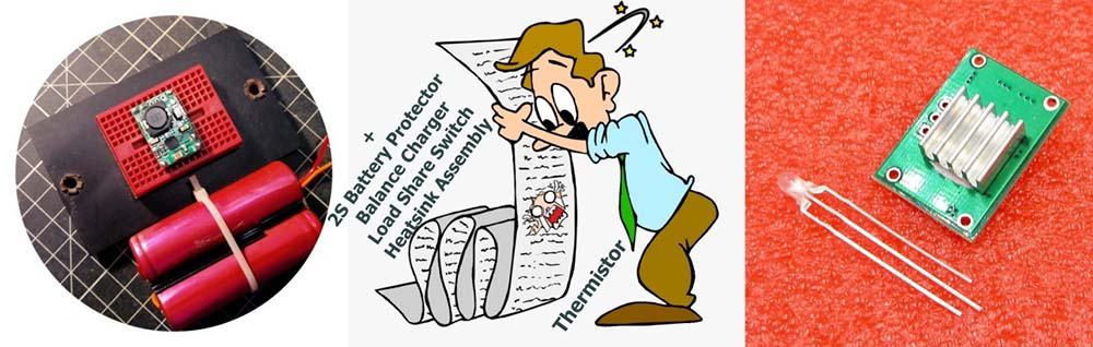
- Option for an external bicolor LED
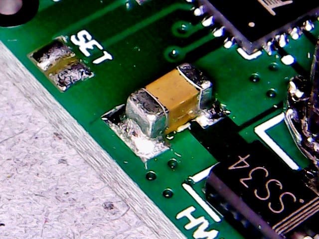
As far as I know, this module can be used for 2A (usually 1.5A) charging of up to 2S Li-ion cells. As stated before, it can be used for charging a single cell (1S) or double cells (2S) wired in series. The 1S/2S solder jumper (SET) on the module which when shorted (CS+VREG) allows charging of 2S cells.
This is what the solder jumper looks like under a soldering microscope:
The module has 2 onboard LEDs – the blue LED is lit when there is no battery connected or when the battery is fully charged. Red LED glows when charging is in progress. See, the module also has some pads for an external bicolor LED (common anode) next to the dc input connection pads (close to the 22uH inductor).
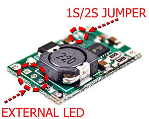
Note that, both the onboard SMD LED and external leaded LED connections are tied to VIN via the same 1K current limiting resistor. This resistor is routed to the center hole of the 3-hole external LED terminus. The leftmost hole – near to the SS34 diode – is for the “charging” LED (red), and the rightmost hole is for the “charged” LED (blue).
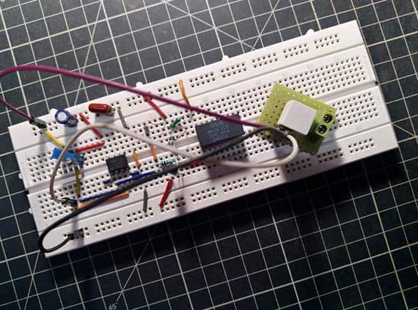
My Quick Trial
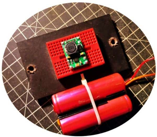
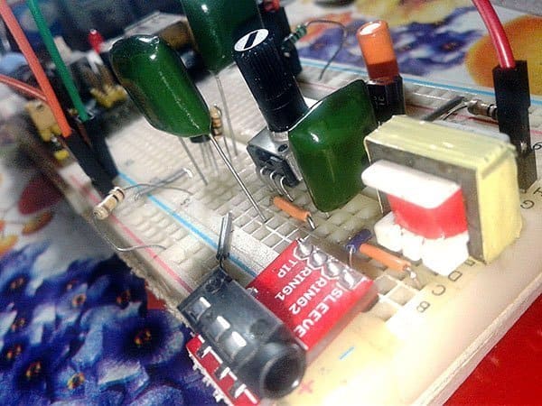
I constructed a belittled 1S/2S Li-ion battery charger for my quick tests using a mini breadboard and a couple of good-quality male-headers and silicon wires (as usual, crap layout and craft – ha ha). The usage of a pair of old 18650 Li-ion (SANYO UR18650Y – https://lygte-info.dk/review/batteries2012/Sanyo%20UR18650Y%201900mAh%20(Red)%20UK.html) cells taken from a discarded Toshiba laptop battery pack considerably reduced the build cost.

Based on the results of my preliminary evaluation, it’s clear that the TP5100 module is certainly a cheerful pick (at least in my case) for a compact 1S or 2S Li-ion battery charger. Yes, the TP5100 module seems to work as advertised – with a 12V/1.5A regulated dc power supply and a partially weak 2S Li-ion battery setup, it successfully charged the battery pack and terminated the charging process at about 8.4V. The only drawback of TP5100 as observed so far is the lack of the balance charger function (so, there may be deviations in cell voltages over time).
But I think I need to remark on some of the key points I entered at the time. So, I’m going to list them below!
- By default, the module is configured in 2A charging mode (Programmable charge current 0.1A-2A), which is a bit high for my current test setup. If we look at the datasheet, we can see that 2A = 0.05Ω setup resistor (two 0.1 Ω in parallel on the top left of the module).
- TP5100 is in fact a dc-dc buck regulator. So, in 1S mode, you have to supply >= 4.5V (5V typical), and in 2S mode, it should be >=9V (12V typical).
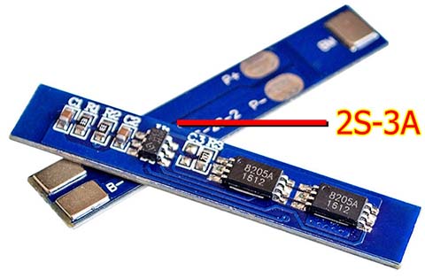
- An external 2S Li-ion battery protection module is required to complete the 2S Lithium battery charger project. Luckily, there are a few 2S-3A 18650 Li-ion battery protection circuit boards in my component drawer. Battery protection circuit boards help to ensure that lithium-ion cells connected in series are protected from over-charging, over-discharging, excess current draw, and short circuits.
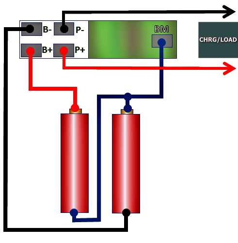
The proposed wiring diagram is shown below. Note that nowadays it is also possible to buy protection circuit boards that include a balance charging feature.
- Improper input power supply and/or incorrect input power supply polarity will immediately kill the TP5100 module. Two of them I have already fried – the rest is a completely burnt TP5100 chip on each module.
- The NTC thermistor connection that is indicated in the official schematic is not available in my TP5100 module, and it seems to be tied to ground with RTRIC for a 10% trickle charge current. See page 9 of the datasheet for more details.
What’s Next?
So far, all the quick test procedures (except the efficiency test) have been accomplished, but the real-world application have yet to be implemented and examined. I also plan to attach an automatic ‘load share’ switch circuit with the TP5100 module. Stay tuned!
you mentioned about reverse polarity input voltage. how about reverse polarity battery? in the specs they listed “reverse battery shutdown protection..”
@chris: Somewhat subtle but according to datasheet (https://voltiq.ru/datasheets/TP5100-datashhet.pdf) TP5100 does not require additional “reverse flow” guard diode. It features reverse battery shutdown protection as well. But being Chinese electronics, everything they say should be taken with a pinch of salt!
i tried to experiment reversing the battery polarity. Aaaand here are the results :
the TP5100 did not blow up or release magic smoke, apparently. but, in 10 seconds, the inductor heats up, battery getting warmer. i immediately disconnect the battery.
Is the tp5100 died? i tried to plug the battery in correct way, plugged 5v input, and the tp5100 works just fine, charging it to 4.25 V and stops.
Summary :
yes it has ” ‘reverse’ battery protection” , tp5100 chip not insta killed, so you have time to unplug and plug it in correct way. but, IT KILLS your battery if you let it sit in wrong way more than minutes. (probably fire hazard!)
so, it’s “half battery protection” for me. Protects the tp5100, but didnt protect the battery…
anyway is there alternatives charging circuit that has full battery reverse polarity protection?
i want to connect 2 Li ion cells in series and want to connect them with BMS and then with TP5100 for charging i want to use it as power backup source for my GPS project mostly TP5100 will be powered 24/7 and in some case if power is lost i want this charging system with 2 cells provide power backup to my GPS project
so i want to know exactly i have to place my GPS project connections for power
Tp5100 is the BMS why U need further BMS..
There is no balanced charging when you use 2S Battery connection method.
@Sudeep: Perhaps you will get an answer from ALI HAIDER.
BTW, BMS is a battery management system, and not a battery charge management system!