This is a simple and 100% safe universal linear charger module for 2S Lithium-Ion (Li-Ion) and Lithium-Polymer (LiPo) batteries with the recommended constant-current/constant-voltage (CC/CV) charging algorithm. Initially charging takes place in the current mode and after reaching the target voltage the charging goes into voltage mode. At the moment the current is small, the battery is charged. The typical target voltage of a 2S battery is usually 8.4V (note that target voltage is not the same as the nominal voltage as it is 7.4V typical).
The design is optimized for batteries of 1000mAh or higher, and the input power source can be any linear/switch mode power supply capable of catering an output current of minimum 750mA at 12V.
| Input voltage | DC12V/1A (max) |
| Battery type | Li-Ion/LiPo |
| Battery cells | 2S |
| Target voltage | 8.4V ± 0.02V |
| Charging current | 0.65A (default) |
| Charging time | 1hr (95% of the nominal voltage) – 2-3hrs (100% of the target voltage) |
| Indicators | Battery Charging/Charged LED & an optional battery okay LED |
- It is not very necessary to remove a fully-charged battery from this charger immediately. There is no problem if the battery remains connected on the charger for sometime
- Although a balancer is beneficial for maximizing energy capability and lifetime of the battery pack, most chemistries have shown very little drift and are okay to charge without balancing for several cycles. Anyway, it’s possible to use a suitable balancer with this charger if necessary
- This charger can’t charge 2S batteries discharged dangerously below 5.8V. In such cases try to trickle charge the battery (using any trickle charger) until 6V is reached, before connected to this charger
Warning!
Li-Ion/LiPo batteries may explode if shorted, overcharged, exposed to high temperature, or otherwise improperly handled
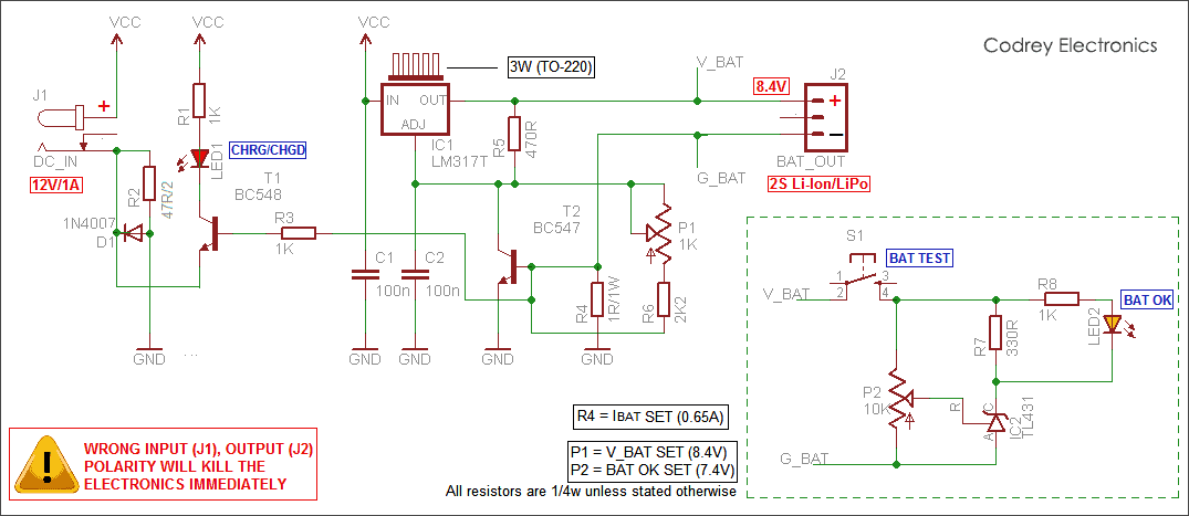
The electronics is in fact a perfect blend of one constant current source and one constant voltage source built around the popular adjustable 3-pin voltage regulator LM317T (IC1). Related capacitors (C1-C2) are added deliberately to increase the circuit stability by reducing possible unwanted noise. Rest of the electronics is a bunch of visual indicators and their supporting components. See the well-annotated circuit diagram included here for a deep perceptiveness.
Initial (one-time) Calibration:
Main Circuit
- Feed DC12V/1A to the circuit via J1
- Carefully adjust preset pot P1 to get exact 8.4V± 0.02V across V_BAT and G_BAT terminals
- Connect 2S Li-Ion/Lipo to J2, and ensure LED1 lights up
Add-on circuit
- Remove DC12V/1A supply from J1
- Connect a fully-charged (8.4V) battery to J2
- Slowly adjust preset pot P2 until LED2 just lights up when pushing switch S1
During first phase of the charging of a highly-discharged battery the heat sink becomes very hot which gradually cools down in an exponential mode. For safety, it’s good to add an extra heat sink if available. Beware! Never directly ground the heat sink because it is linked to positive rail of the battery
- Power up the charger circuit from a 12V/1A external power supply. Any unregulated/transformer-based ac adapter or smps can be used. Ensure correct polarity (+/-) else circuit will be fried within seconds
- Connect the 2S Li-Ion/Lipo battery to the charger circuit. Ensure correct polarity (+/-) else circuit will be fried within seconds
- Now the red LED (CHRG/CHGD) lights up instantly to indicate correct charging process. If the battery is a fully-charged one, or a faulty one, the LED will not lights up. Otherwise the LED glow diminishes from bright to dim (finally dark) with the progress of ongoing charging process
- Usually within 1hr, the battery level goes to 95% of its nominal voltage (95% of 7.4V). And reaches upto the 100% of its target voltage (8.4V) within 2-3 hrs thereafter
- When the battery is fully charged up to 8.4V, the red LED switched off automatically to indicate a full-charge state. Charger circuit will automatically switched off too. Sometimes, a very faint glow in the LED might become visible. It’s not a fault, but the indication of a harmless leakage current; don’t care!
- Depending on the type of the external charger, and the chemistry of battery pack connected, it may become necessary to wait up for a little more time to achieve the nominal and/or target voltage
At anytime during the charging process, user can test the condition of connected battery using the (optional) “BAT TEST” button. When the button is depressed, “BAT OK” indicator will lights up only if the battery is charged upto its nominal voltage (7.4V) or higher than the normal voltage (anywhere from 7.4V TO 8.4V). In short, this is a trustable notification, signalling the battery is healthy and ready for veritable service!
Design Maths (refer schematic)
- LM317T(IC1) can handle safe currents up to 1.5A if heat-sinked adequately. Here the charge current is limited to 650mA by R4 (1R/1W). Formula: I (charge) = 650mV/R4 = 650/1 = 650mA
- Turn off threshold of LED1 is determined by R2(47R/2) and D1(1N4007). Here the threshold is just below 25mA. Formula (I cutoff) = 0.6/R2 = 0.6/ (47/2) =25mA~
- In the prototype TO-220 type 3W heatsink is used with LM317T(IC1). As it’s unsafe to run LM317 above 60 degree C, replacing the existing heat sink with a lower thermal resistance type might become good to ensure better reliability. Formula: Maximum Thermal Resistance = (60-Ambient Temperature)/Power. For example, if ambient temperature is 30 degree C, and power is 3W,then Thermal Resistance = (60-30)/3 = 10 degreeC/Watt
Hello, I had couple of questions about your circuit. I see two resistors (R4 and R2) with labels “1R/1W” and ” 47R/2″. What do those labels mean? I assume the “1R/1W” means 1 ohm at 1 watt and “47R/2 means two resistors in parallel, but I am not sure. Any clarification would be appreciated.
Stefan LeClair: You’re right! The 1R/1W means 1 Ω/1W, and 47R/2 means two 47Ω resistors in parallel, Thanks!
Thank you for your answers to my previous questions. I have built the circuit and had a few more questions concerning operation.
What part of the circuit allows the user to leave the battery connected without damage to the battery? I assume it has something to do with the second transistor BC 547 but I am not quite sure.
From my understanding, the charging current starts at 650mA and then slowly decreases as the battery is charging, hence the red LED becomes dimmer. Is this correct? My charging LED is not functioning but the circuit is charging correctly so I am debugging.
What is the purpose of the TL431 shunt voltage regulator in the battery testing circuit?
Thanks for your help.