This prefatory article focuses on Avalanche pulse generators commonly used to generate fast rise time pulses. Often fast pulses are required when measuring slew rate or propagation delay, and for sampling. Fortunately, avalanche breakdown of a bipolar junction transistor (BJT) can be exploited to generate such special pulses with ultrafast rise and fall times.
Bipolar Junction Transistor & The Reverse Avalanche Way
Let me start with a ‘reversed’ idea! The circuit used for demonstration here is an uncommon LED flasher based on a reversely connected BJT. When wired in reverse (when collector and emitter are reversed) avalanche magnitude of a BJT is usually lower than its normal avalanche voltage. Note that when BJTs are operating in reverse avalanche region as tried here, they can also be called as negistors (higher the current, lower the resistance). Well, the following circuit diagram shows you one simplest form of a reverse avalanche pulse generator.
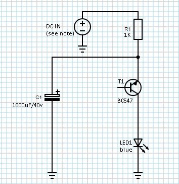
Working principle of the circuit is extremely simple. The 1000uF capacitor (C1) is charged via a 1K current limiting resistor (R1). Initially theBC547B transistor (T1) is in nonconductive state, but when the voltage across the reservoir capacitor reaches a certain level, the transistor enters the avalanche breakdown mode, and exhibits negative resistance. Consequently, the capacitor discharges rapidly through the LED (LED1). The voltage across the transistor drops until the avalanche mode can no longer be sustained, and then the it move back into its normal state and becomes nonconductive again. This cycle continues and as a result the rapid discharging through the LED demonstrates itself as short flashes. Flashing rate of the LED counts heavily upon the RC constant and the transistor’s breakdown characteristics. For a typical 5mm blue LED, no current-limiter resistor is required as the duration of the current flow is extremely short. But if you’re using a different LED you may need to include one current limiting resistor to protect the LED.
I made the test using the same circuit setup shown above, and found that the minimum voltage required for the circuit to operate is just about 12.5V. Since it’s also noticed by me that the same transistor from various manufacturers/sellers can comport quite differently, your results might be rather dissimilar than what I have here. Likewise, as the input supply voltage changes, the pulse interval changes fairly as well.
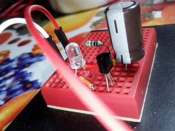
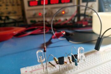
Below is what my finished test circuit looks like made entirely from junk box parts.
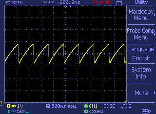
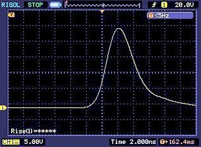
The casual oscilloscope capture below shows the waveform measured at the anode with respect to ground (0V), when the supply voltage is in 12.5V – 14.5V range. You can also watch a quick test movie included elsewhere in this post.
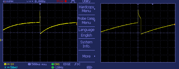
The next waveform at the emitter of the transistor (T1) denotes the charge and discharge of the capacitor (C1), probed while the circuit was powered with a supply voltage of 14.5V. Keep in mind that when running a BJT in reverse avalanche mode, the rise time is not very neat and fast as in the standard avalanche mode (one of the useful benefits of the standard avalanche pulser is its extremely fast rise time in sub-nano second). My quick experiments showed that rise time of the circuit used by me is more piteous if compared with that of a standard avalanche pulser!
Bipolar Junction Transistor & The Standard Avalanche Pulse Generator
A standard avalanche pulse generator circuit basically relies on the negative differential resistance in a bipolar junction transistor’s avalanche breakdown region to form a relaxation oscillator. Below is the simple (and quite popular) circuit of a typical avalanche pulse generator based on a 2N3904 transistor. Note that you can make a try to substitute the avalanche transistor 2N3904 with another available general-purpose transistors such as 2N2222, 2N4441, MPSA42, MPSA44, BC107, BC337, S9014, S8050, etc., not every general-purpose NPN transistor can faithfully avalanche, though!
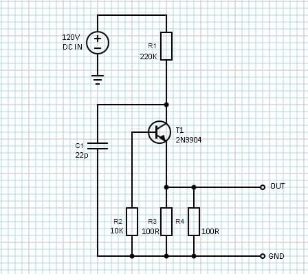
In this circuit, components R1 and C1 determines the operation frequency, and it’s at roughly 30 kHz. To deliver the high voltage demanded by the avalanche pulse generator, you’ll obviously need a dc-dc boost converter. Since the current here is very low, a regulated high voltage dc output is not very crucial. You can find numerous dc-dc boost converter (high-voltage version) circuits everywhere on the web. Take any one of those tried and tested circuits – it’s simple (http://www.aholme.co.uk/Avalanche/Avalanche.htm).
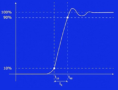
If everything’s fine, probably you’ll get a pulse output across the load resistors (R3-R4) similar to the one shown below captured with a 100MHz bandwidth oscilloscope . A very fast oscilloscope (not mine, unluckily) is required to do it justice. See it’s a 2.5nS rise time which translates into a bandwidth around 140MHz (an impedance mismatch surely slowed it down, but not bad).
Rise Time & Bandwidth?
Rise time is crucial parameter in both analog and digital systems as it’s the time taken for a signal to cross a specified lower voltage threshold followed by a specified upper voltage threshold (in digital systems, however, it describes how long a signal spends in the intermediate state between two valid logic levels).
I hope you all know that rise time can be used to measure Gaussian bandwidth using the simple formula: BW = 0.35 / T where BW = bandwidth and T = rise time. This is the commonly used relationship between the rise time of a signal and its bandwidth. If we want a rough measure (a rough approximation) of the highest frequency components in a signal, it’s about 0.35 divided by its 10-90 rise time. The underlying assumption here is that the signal is the response of a 1-pole filter and the bandwidth is the -3 dB point of the filter. Since there’re ofcourse other ways to estimate the connection between the bandwidth and rise time in a signal, I’ll try to explain the rest through another article, subsequently.
In summary
I’ve devised a way to employ bipolar transistors operated in avalanche breakdown mode to construct great avalanche pulse generators. Such generators of nanosecond-scale pulses of voltage (or current) can be used to drive electro-optical devices such as laser diodes. An elucidated article on a do-it-your self laser diode pulser project will come after in time. Much fun!
Further Reading
Some very good advice and an example of an avalanche pulse generator from the celebrated analog guru Jim Williams can be retrieved from Linear Technologies AN47 application note.
https://electronicprojectsforfun.files.wordpress.com/2017/10/jimwilliamsan47applicationnode.pdf
A few References
Very good article.
Thank you.
I built your circuit and tested an old Tektronix 2430a oscilloscope set-up. It was easier for me to use the onscreen display readout than using an older analogue unit I have.
I do want to test out the analogue unit. Though I suspect that it will be considerably harder for me. I am a very basic hobbyist.
I was on another website and they used BW = 0.42 / T as a secondary number. Do you know what this 0.42 number refers to?
Keep up the good work!
Banman: You’re welcome! Thanks for the feedback.
Regarding the analog oscilloscope measurements, hope this post helps you (https://www.utmel.com/blog/categories/oscillator/how-to-understand-the-oscilloscope-bandwidth). Please go through it and let me know if you need more clarification. Cheers!
Actually, that’s the website I found the reference to the modified equation.
BW = 0.42 / T
Am I correct l correct in thinking that the 0.42 is used when looking at high performance oscilloscope set-ups?
@Banman: Then let me make it a little more clear!
Throughout history, oscilloscope frequency response tended to approximately follow the rule “Bandwidth x risetime = 0.35”. Note, rise time is defined as the time required for a signal to move from 10% to 90% of a rising wave-form.
Simply, the old rule of thumb uses the constant 0.35 (still more conservative in my view) but most real-time digital oscilloscopes nowadays more closely follow the rule “Bandwidth x rise time = 0.45” (this corresponds to a much steeper frequency roll-off above the specified bandwidth).
Hope this helps you at this point. Anyway I won’t go into too much detail now. Maybe I’ll put more of my thoughts on this into an article later. Thanks!
Hi T.K.Hareendran,
Thank you for your in-depth knowledge on this subject.
Very good explanation, makes sense.
It all seems to correlate with the oscilloscope’s rated bandwidth I have here.
I have been using the calculation quite a few times, tabulating them and then averaging out the results to get a somewhat true to life representative oscilloscope bandwidth number.
I really appreciate your help and time in helping me get my head around some very important concepts.
Thank you.
@Banman: I’m so glad it’s helpful! You’re most welcome 😍