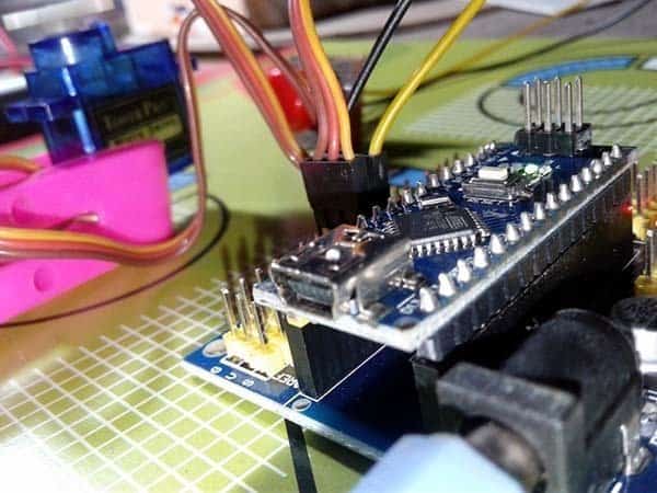
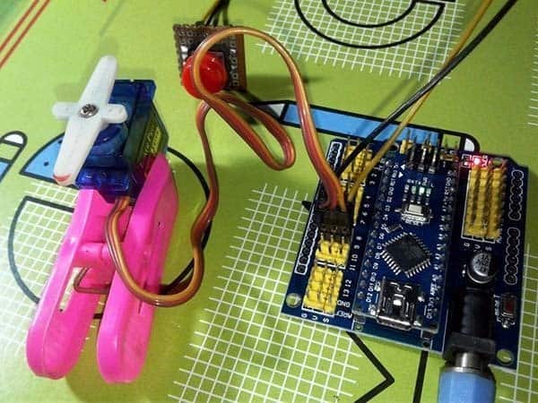
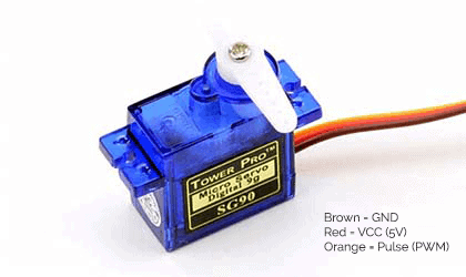
Here’s a nice little project of a quick servo tester with Arduino Nano (v3) microcontroller board. Another key part in this basic project is a cheap Arduino Nano(v3) expansion shield. The hardware setup is extremely simple and straight forward as with just a push button switch you can ‘sweep’ the servo motor under test to verify its functionality. My setup was tested with the very common Tower Pro SG90 micro servo motor.
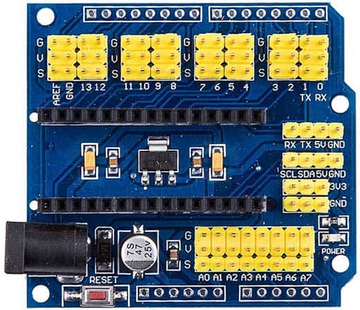
Arduino Nano(v3) is a standalone 5V/16MHz breadboard-friendly microcontroller board based on ATmega328P microcontroller which can be powered via the onboard Mini-B USB interface, 6-20V unregulated external power supply (pin 30), or 5V regulated external power supply (pin 27). However, using an Arduino Nano(v3) expansion shield with Arduino Nano(v3) gives us much more convenience and flexibility just because of its distinctive métiers. The Nano(v3) microcontroller board will drop right into the shield, and the shield then offers full access to all I/Os neatly arranged in a triple ‘Gnd – Vcc – Signal’ (G-V-S) layout, especially good for external sensors/actuators. In addition to the RESET button, there’s also a standard DC input socket mounted on the left-hand side to feed unregulated dc supply (9-12V recommended) from an external power supply/battery. Furthermore, the Serial (RX, TX), I2C (SCL,SDA), 5V, and 3.3V (from an onboard voltage regulator) are also brought out onto the right-hand side of the shield.
A servo is a small dc motor with some speed-reduction gears, a position encoder on the motor shaft, and an electronic circuitry to control the motor operation. Usually, a servo motor have a three pin interface – Vcc, GND, and Signal. The control input is accepted as a pulse proportional modulation (PPM) signal between 1ms and 2ms (out of a 20ms time period) for a movement range in 0 to 180 degrees. The angular movement is determined by the duration of the pulse applied to the control input.
So now that we know what’s behind the hardware parts, let’s try it. The connection to the servo must be made on the shield’s I/O attached to D9 while the button switch must be wired to the I/O for D8.
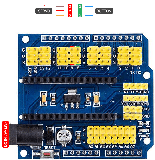
Here’s an important note: Although the entire setup can be powered from an external 9-12V dc power supply or battery through the dc input socket, it’s highly recommended to use a separate power supply for the shield (9-12V unregulated) and the servo (5V regulated) under test. In order for everything to function properly, the ground connections for the shield and the servo power supply must be tied together. Also make sure to properly orient the servo plug when you plug it into the I/O header as servo connection leads are color-coded always, but aren’t universal!
The connected servo can be run by pushing the button switch. First push (and release) of the button switch will increment the servo horn until it reaches a value of 180 degrees, and a similar button action thereafter decrements the servo horn till it reaches to 0 degrees. During initial power-up/reset, the servo horn will be locked ( as usual) at its mid position (90 degrees). See, we are going to use a small code (Arduino Sketch) to start with the concept.
Start the Arduino IDE, Select “Nano” (Processor: ATmega328) as the board, connect the USB cable between your PC and the Nano(v3), and type (or copy-paste) the Sketch. Next, Verify (compile) the sketch for any syntax errors, and if there are none, Upload the sketch to Nano(v3). Once completed, remove the USB cable and plug the Nano(v3) in the expansion shield to proceed further. If everything is wired properly, the servo motor under test should go through the pre-defined test routine.
/*
 * Quick Servo Tester NanoV3
 * Hardware: Arduino NanoV3 & NanoV3 Expansion Shield
 * Servo Motor (Tested): Tower Pro SG90
 * Authored By: T.K.Hareendran/2018
 * Publisher: Codrey Electronics
 */

#include <Servo.h> // Required Library
const int servoPin = 9; //Servo Signal O/P Pin
const int buttonPin = 8; //Button Switch I/P Pin
int buttonState = 0;
int directionState = 0;
Servo myservo;
int pos = 0;

void setup() {
  myservo.attach(9); // Servo Object
  pinMode(buttonPin, INPUT); // Pin 8 as I/P
  digitalWrite(buttonPin, HIGH); // Enable Internal Pull-Up
}

void loop() {
  buttonState = digitalRead(buttonPin);
  if (directionState == 0) {
    if (buttonState == LOW) {
    directionState = 1;
    for (pos = 0; pos < 180; pos += 1)
      {
        myservo.write(pos);
        delay(20);
      }
    }
  } else if (directionState == 1) {
    if (buttonState == LOW) {
    directionState = 0;
    for (pos = 180; pos >= 1; pos -= 1)
      {
        myservo.write(pos);
        delay(20);
      }
    }
  }
}
Did You Know?
Nano(v3) can test two servos with the same setup! Just try to create a second instance of the servo object for Pin10 (D10) so that each object represents a physical servo attached to the Nano(v3). Pretty cool, isn’t it?