 Aware that a particular circuit is needed to measure electrical conductivity (EC) of a liquid. Since the conduction of current through a water solution is mainly dependent on the concentration of dissolved ionic substances such as salt, conductivity ranks as one of the key inorganic water quality parameters. There’re so many different approaches to measure EC, but the most common method is the use of a pair of submerged probes as the part of a resistor divider, and measuring the resistance between them (Resistance =1/Conductance). I’m sure there’re many other great ideas that I’ve yet to find out, however, now I’d like to introduce one quick and easy circuit of a do-it-yourself electrical conductivity (EC) sensor based on the evergreen 555 tiny timer chip!
Measuring electrical conductivity with metal electrodes
As you may well know, direct current (DC) must not be allowed to flow through the submerged metal probes of the EC sensor, or else the probes (electrodes) will corrode. The resistance of the oxide layer that quickly formed on the metal surface is nonlinear, and eventually making the reading imperfect. The alternating current (AC) probe excitation can be tacked on to avoid this problem by reversing the polarity of the current flow many times per second, so that electrode polarization takes place at either probe.
Role of 555 timer chip in the electrical conductivity sensor
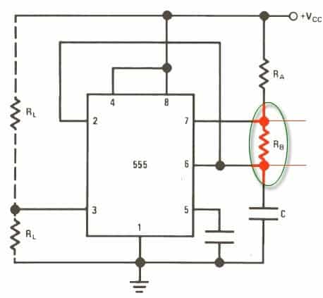
A dc operated circuit naturally calls for a suitable oscillator to provide ac excitation. You can of course build a 555 IC based oscillator (astable multivibrator) circuit to blink an indicator at a tempo that’s inversely proportional to the conductivity of the solution under examination. When 555 IC is wired as shown in next figure, it will trigger itself and free run as a multivibrator. The external capacitor C charges through RA + RB and discharges through RB. Thus the duty cycle may be precisely set by the ratio of these two resistors. It’s an extremely simple task because you just need to replace the resistor RB in the basic 555 IC astable multivibrator circuit with a pair of sensor probes/electrodes to start the play. On the other hand, you can attach the electrodes in parallel with the existing resistor RB. Did you get it? Here’s the web link of a similar idea/project https://publiclab.org/wiki/555-conductivity-meter
An entirely different astable approach
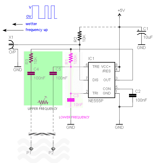
Granted that it’s a good theme, all the same I still want to go with another idea. Following is the basic circuit diagram of my Easy 555 EC Sensor!
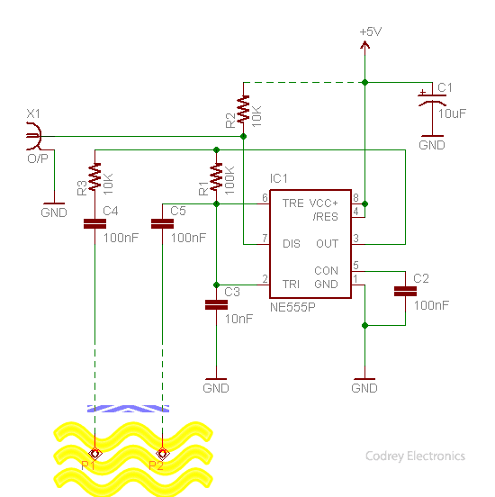
At this time, the NE555P (IC1) not only provides enough AC excitation but also a ‘tricky’ galvanic isolation. Note that IC1 works in its direct feedback mode, with a square wave on its totem pole output (Pin 3) charges or discharges the 10nF capacitor (C3). If the electrodes (P1-P2) are in dry state, the 100K resistor (R1) limits the minimum oscillator frequency in Hz range. But when the electrodes are short circuited, the 10K resistor (R3) in series with the two 100nF capacitors (C4+C5) and the electrodes set the upper frequency in kHz range.
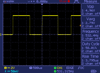
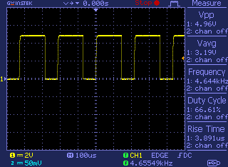
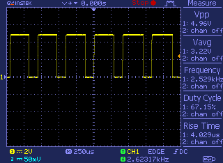
In my case, the quick breadboard setup isn’t prepared with 1% resistors (and stable capacitors) so the results aren’t exactly as on paper, but has an approximative ‘open-probe’ frequency of 530Hz, and a ‘short-probe’ frequency of 4.5kHz. Notably, it’s roughly in 1.5kHz – 2.5kHz range with a moderate moisture level across the sensor probes/electrodes spaced a few millimeters apart.
Now you can go through a couple of cursory oscillograms recorded while I was testing the output signal of my breadboarded circuit powered by a regulated 5VDC power supply. As you might noticed, the output frequency is delivered from the open-collector “discharge” terminal (Pin 7) of the 555 IC. The 10K pull-up resistor (R2) is included deliberately to output a ‘cool’ square wave that can be extended further to a microcontroller-based readout circuit, a data logger device, or an irrigation controller.
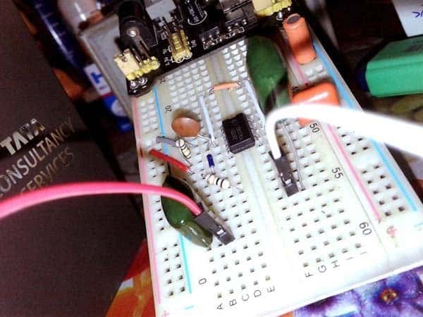
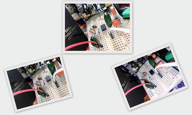
And, see a close-up of my quick breadboard setup.
It’s time to do your homework (tweak it)
In order to build your own version of the electrical conductivity sensor, you might need to adapt the basic design as per your specific application. For example, you can set a different lower frequency by changing the value of RC timing components R1 and/or C3. Likewise, the upper frequency can be varied by changing the associated components R3,C4, and C5.
Keep it in mind that the presented circuit is merely a basic one i.e. it’s only a ‘single-node’ electrical conductivity sensor probe circuit, certainly not a full-fledged electrical conductivity meter, precision water/soil moisture level sensor, or a ‘fit and forget’ irrigation controller. If you plays along with the exact basic circuit diagram (Fig 3), you’ll eventually get one EC sensor having similar (or near-similar) specifications:
- Supply voltage: 5VDC (regulated)
- Frequency output: ~ 500Hz (dry) to 5kHz (wet)
- Voltage output: ~ 3V (dry) to 3.4V (wet)
The open-collector/pulled-up output can be measured using a ‘count’ or ‘period’ function on a data logger. Alternatively, the raw frequency readings can be interpreted by a microcontroller to establish thresholds for irrigation or other actions. I’m pretty sure an Arduino (or the like) will work well for the rest of the ‘dreamed up’ electronics, but not going to cover that idea in this post. You can see more on that concept in a later post, and it’s going to be a good one for sure!
A few ideas for adaptation
- Tiny tone decoder circuit (T.K.Hareendran) https://www.codrey.com/electronic-circuits/tiny-tone-decoder-module/
- Sound whistle frequency tone detector decoder module (Electrodragon) https://www.electrodragon.com/product/special-sound-identifier-module/
- Whistling detection Arduino (Electronoobs) https://electronoobs.com/eng_arduino_tut19.php
how it changes back into dc for fed in microcontroller
Aryna: You don’t need to convert the output pulse into dc voltage. Read this post to get some ideas https://www.arrow.com/en/research-and-events/articles/data-logging-with-arduino-tutorial . And stay tuned for the second part of this article scheduled to be published in January 2021. Thanks!
Great work! I’ve built this and it looks very promising for a little project I’m building and I’m getting similar values for the wet and dry frequencies to those you mentioned. For now, I’ve used 3.1 Volts output from an LM318 to power the 555 circuit. I have connected to an Arduino Uno and now reading the pulse frequency so I need to make up some calibration standards now to figure out how linear and reproducible the readings will be with my particular cell arrangement. I plan to use a Pi, instead, to collect and show data, eventually.
mark simmons: Thanks!
First of all, let me say that it would be better to replace the NE555 with its CMOS version (LMC555), because it seems that you want to use a 3V power supply.
As you might noticed (and as already pointed in the article), it’s easier to measure the open-collector/pulled-up output with a datalogger. But that would not be interesting for an avid maker, I know!
So, when it comes to the microcontroller application, sorry, I almost forgot about the promised sequel to this article. However, I will do it as soon as possible.
In the meantime, you can walk through the original source of my inspiration https://thecavepearlproject.org/2017/08/12/measuring-electrical-conductivity-with-an-arduino-part1-overview/
Good luck with your project…
Thanks for the advice about using the CMOS version. I look forward to your next article on this subject.
How do I calculate the values of R3, C4, C5 to achieve an upper frequency of, say, 8KHz instead ? I’m reaching a frequency limit with some of the test chloride standards I’m testing but had a good linear regression fit until then.
@mark: You’re welcome!
I will post the updated version (perhaps more user-friendly) as soon as I can. Thanks!
As you know, setting the 555 astable frequency (upper range) is a bit tricky because it always depends on the resistance value between the probes (roughly, proportional to the moisture level).
So I can not give a pragmatic suggestion to tweak your prototype which is far away from me. I hope you understand. Anyway, replace R3 with a multiturn potentiometer so that you can do it in an empirical way.
Further, you can go through this documentation to get a bit better insight http://www.emesystems.com/smx/documents/SMX_2018.pdf
Best Wishes…
Hi sir,
This is great design, maybe a stupid question, what is X1 in your schematic?
Flynn: X1 in the schematic is an output connector. This is not a critical part, so you can use any available connector to feed the output signal to an external circuit. Thanks!
what is the purpose of this connector then?