 There are different types of pulse width modulation (PWM) circuits out there online, but for the purposes of sharing a new post, I am showing you an Arduino Universal PWM Driver project at this time!
Okay, let’s walk you through the journey to give a sense of what is involved in order to do this correctly. I will simplify the setup procedure here to give you a sense of the work required, but if you make this kind of project for the first time, then seek the assistance of an experienced electronics hobbyist as he/she can help you to do this in a faultless way.
It starts with a simple piece of code – the so-called Arduino Sketch – tailored exclusively to set up the Arduino microcontroller as a fixed frequency PWM signal generator but with a variable duty cycle feature.
/*
 * Universal PWM Driver v1.1
 * Adjustable PWM Drive for Power-Hungry Devices
 * With Isolated Power Driver Hardware !
 * Experimental Arduino Uno/Nano Sketch by T.K.Hareendran / 6-2021
 */

int drivePin = 9; // PWM OUT TO POWER DRIVER = D9
int PreviousPotValue = 0;
int Threshold = 0;

void setup()
{
  Serial.begin(9600);
}

void loop()
{
  int PotValue = analogRead(A0); // 10KB POT IN = A0
  int PWMValue = PotValue / 4;
  analogWrite(drivePin, PWMValue);
  Threshold = abs(PotValue - PreviousPotValue);


  if (Threshold >= 10) {
    int PWM_DutyCycle = ((float)PWMValue / 255.0) * 100.0;
    Serial.print("PWM Duty Cycle = ");
    Serial.print(PWM_DutyCycle);
    Serial.println("%");

    PreviousPotValue = PotValue;
  }

  delay(2);
}
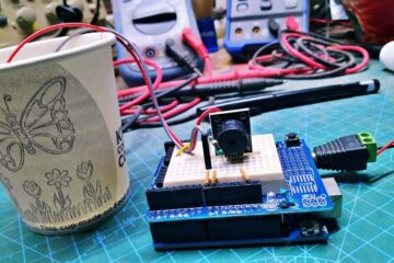
The above code seems to work pretty well, now with this simple Arduino Uno R3 hardware setup.
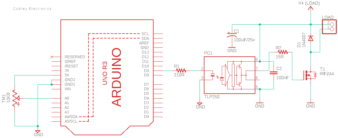
The Arduino PWM driver uses the above code in combination with a potentiometer to vary the ‘power’ to the load connected at the final output stage in pulses. The duty cycle of these pulses depends on the voltage inputted on one analog input pin of the Arduino. In this way, the load can be ‘regulated’ in a very smooth way.
The setup uses a 10KB potentiometer (TM1) to send a variable voltage (0-5V) to the first analog input (A0) of Arduino Uno. The PWM signal output is available through the D9 pin of the Arduino Uno board. The setup also has a 9-12VDC supply to power the Arduino hardware assembly, not shown here though.
Look, the “10KB” denotes that the potentiometer is a linear type 10KΩ potentiometer! Here, 10K is the maximum resistance the potentiometer will provide, and B indicates it is a linear taper. A logarithmic potentiometer (also sometimes called an audio taper, due to how our brains perceive increases in audio volume) is commonly labeled as A – for example, 10KA.
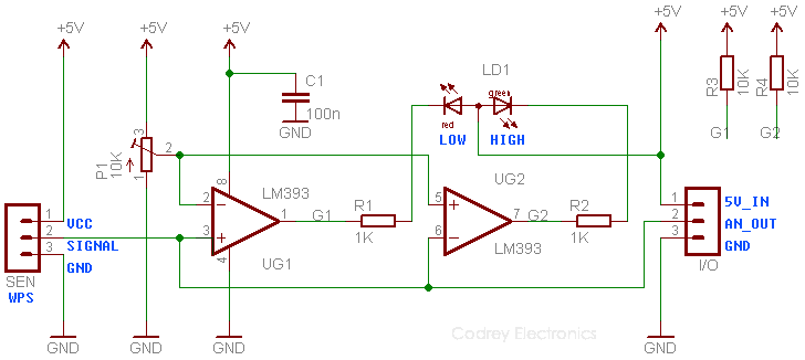
Next (and the final) part of the setup is the “Power Driver” which is nothing but a galvanically-isolated Power MOSFET circuitry able to drive common power-hungry dc loads like lamps, heaters, motors, solenoids, etc. I put together a previous design here because I was happy with it yet (https://www.codrey.com/electronic-circuits/power-mosfet-module-for-microcontroller/). The power driver circuitry will accurately regulate the load power but that process is governed by the potentiometer, that’s it.
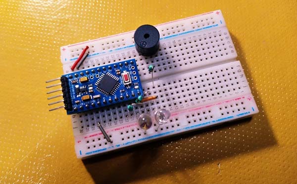
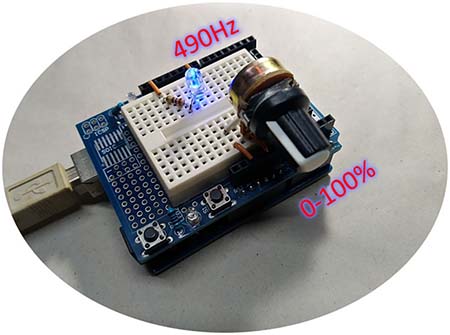
The best way to test your build is to run the Arduino assembly alone at first by connecting an LED (with a 220Ω series resistor) to D9 (see a snap of my attempt below). After successful evaluation, you can test your entire build by linking the power driver circuitry’s input to Arduino’s D9 output.
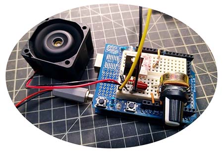
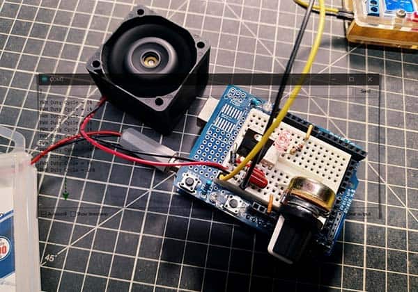
I tested my prototype well with different types of electric loads. The first experiment was conducted with a 12VDC heatsink cooling fan, and you can see a random snap of that work below. At this time, note that the code given here has the ability to display the duty cycle value in the Arduino Serial Monitor window as well.
Like I mentioned in many articles published before, to control the speed of a motor (or the brightness of a lamp) you can use pulse width modulation or PWM. Imagine instead of turning the motor/lamp continuously on, you turn it on and off quickly. The frequency of the on-off action would be so rapid that the motor/lamp would not completely turn on or off, but it would work at a speed/intensity that is proportional to the on-time in every period. So, by adjusting the pulse width of the on-time in every period you can regulate the load (duty cycle is the percentage of on-time over one period). And this is basically pulse width modulation (https://www.fluke.com/en-in/learn/blog/electrical/what-is-duty-cycle).
And finally, you know that a motor is basically an inductor, and when the switch is closed, it charges to some current, and when the switch opens, it wants to continue discharging its current. But since it can’t do it at that time, its voltage spikes out very high.
However, with the addition of a freewheeling diode/flyback diode (D1 in the schematic), the motor has a path through the freewheeling diode to discharge its current and the voltage of the motor at the switch side will not exceed the supply voltage plus a diode drop. Yes, the freewheeling diode has a crucial role in preventing over-voltage and damaging the switching element when the universal PWM controller is used for driving inductive loads. Further reading https://instrumentationtools.com/freewheeling-diode-working-principle/
Did you like this little idea? Hope so! Anyway, let me know if you need more clarity and/or more help to complete this project.