In many posts, we saw how to use a common transistor as an electronic switch to drive power loads of voltage and current mightier than those we could deliver with the I/Os of a standard microcontroller. In this post, we will see how to build the same circuitry using a power MOSFET, rather than a BJT, together with an isolated power MOSFET gate drive IC.
Well, let’s start with the schematic!
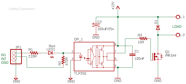
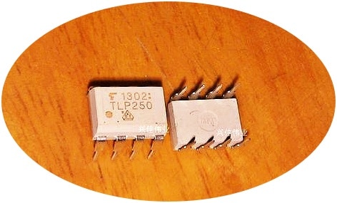
As you can see in the above schematic, the power MOSFET module design is centered around Toshiba’s TLP250 (OP_1) photocoupler which consists of an infrared emitting diode and an integrated photodetector in an 8-lead DIP package.
Here the TLP250 is employed to drive an IRFZ44 power MOSFET (Q1) which is able to handle really big power loads. Galvanic isolation provided by the photocoupler separates the input and output supplies so that energy flows through a field rather than via electrical connections. Thus, it enables power transfer between two circuits that must not be wired directly. At this point note that using a photocoupler and isolated power supply is the common method to have galvanic isolation.
- TLP250 Datasheet https://www.mouser.in/datasheet/2/408/TLP250_datasheet_en_20190617-1134314.pdf
- IRFZ44 Datasheet http://www.irf.com/product-info/datasheets/data/irfz44.pdf
The 12V DC power MOSFET module design presented here is tailored to work with 5V and 3.3V microcontrollers, and it has two input points – IN1 and IN2. The default input IN1 can be used to input TTL level signals from 5V microcontrollers while the auxiliary input IN2 works better with 3.3V microcontrollers. The GND connection is common for both inputs.
In addition, exactly the same as with a BJT driver, in case of using a power MOSFET to drive an inductive load (motor or electromagnet) we must include a flyback diode to provide a path of minimum resistance, which allows to dissipate the induced currents generated by the magnetic field of the inductive load when it’s switched off. Therefore, the option for incorporating a flyback diode (D1) is also available in the design. Looks good?
Now it’s worthy to note again that inductive flyback refers to the voltage spike created by an inductor when its power supply is suddenly reduced or removed. This voltage spike occurs because the current flowing through the inductor cannot change instantly. The rate at which the current can change is limited by the inductor’s time constant. The flyback voltage generated by inductive loads can potentially damage the component being used to open and close the circuit. I’ve provided an article link for further reading, which can be found below:
- Inductive Flyback and Flyback Diodes https://learn.digilentinc.com/Documents/390
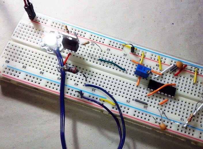
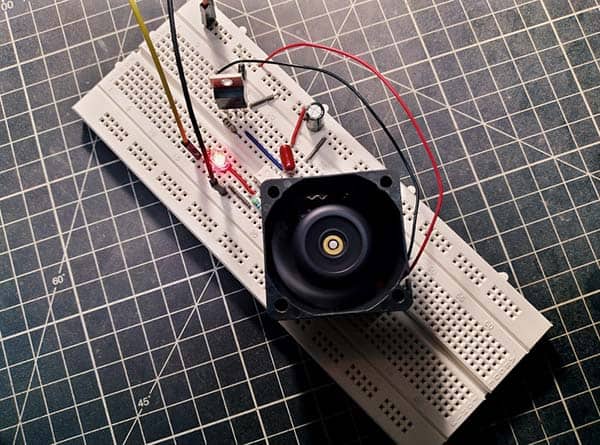
As usual, I made a quick prototype on a standard breadboard and used a powerful 12VDC BLDC micro cooling fan as the output load.
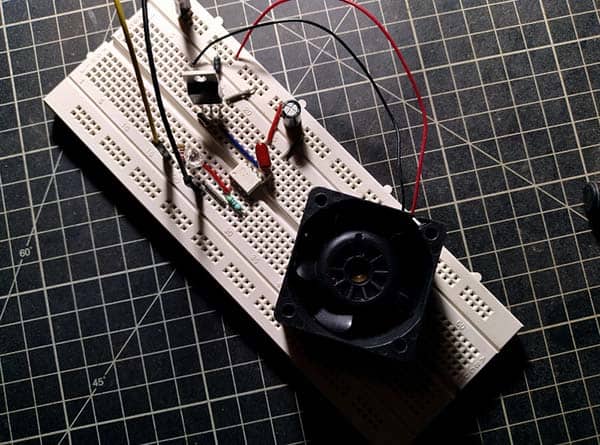
During the initial test, the input pulse was taken from an Arduino Uno board loaded with a slightly modified “BlinkWithoutDelay” example code. The Arduino is powered by an external 9V power brick, and a regulated power supply for the 12V rail. And yes, it worked as anticipated!
Actually, the TLP250 photocoupler is an obsolete component but I’ve a few more in stock. Obsolete components can still be sourced from certain online storefronts, and those components can be used if the design is only going to be produced at low volume. However, one of the risks with sourcing and using obsolete components is that the quality may not be as high, or you may accidentally be given counterfeits. So, it is important to locate a trustworthy supplier because such a vendor will provide you with obsolete components which have been fully tested and are good to use.
Perhaps the best practical way is to consider this Power MOSFET Module design as a mere ‘template’ and stay up-to-date by finding an identical replacement component (or as close a match as possible will suffice). It seems Toshiba’s TLP250H(F) photocoupler will be a wise pick for updating this little project because its package and characteristics are almost the same (https://www.mouser.in/datasheet/2/408/TLP250H_datasheet_en_20151224-1915943.pdf).
And that’s it. I hope that this little post together with a TLP series photocoupler gate driver from Toshiba will help you to design and build your own isolated power MOSFET module(s) at ease. Spotted a mistake? Enjoying this project? Any opinions on upcoming articles? Let me know!