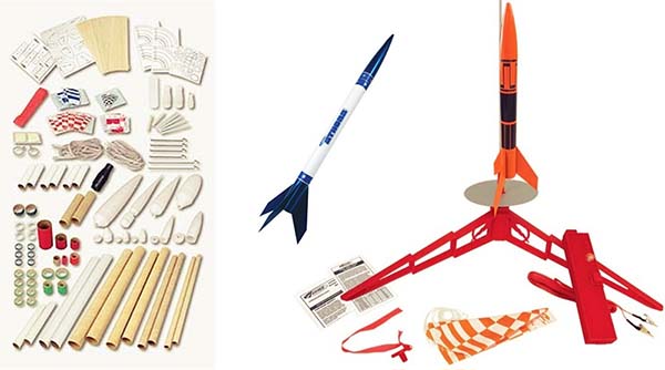
Most commercial model rocket launch controllers available to buy are either expensive or do not have desired features. After a lot of Googling, I found nothing that fits my little budget. Actually, I wanted a universal launch controller that could work with almost all commonly available model rocket engines/motors, as well as being easy to set up and run. So, I designed and built a crude version my own!
This article describes the design and construction of a simple and safe launch controller for the ignition of model rocket engines/motors. The controller will cater to ample electrical power to ignite nearly all low-voltage igniters.
All about model rocket engines/motors http://www.lunar.org/docs/handbook/motors.shtml
Circuit Diagram & Design Description
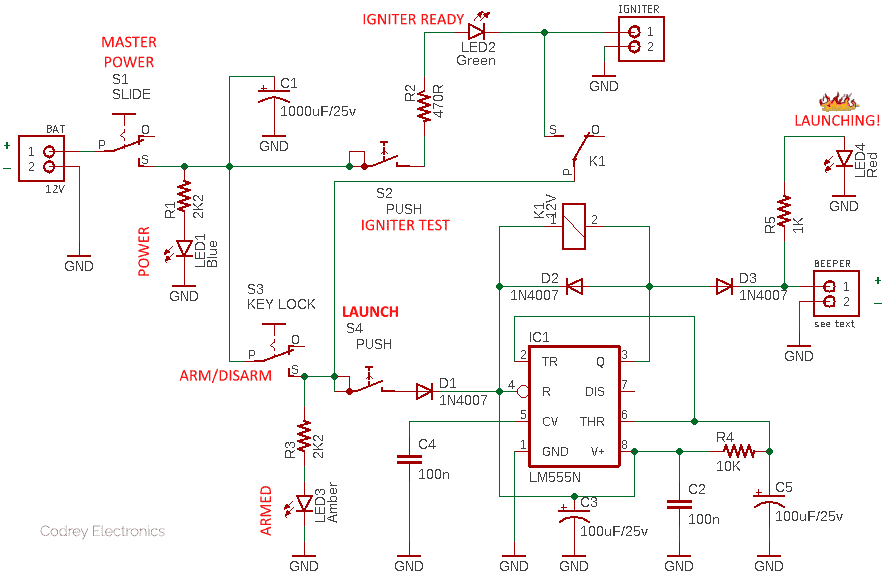
This is the well-annotated first version (v1) schematic of the model rocket launch controller.
Note that no luxurious features are included in this basic design to simplify it, but you can easily add your own to suit your needs. I only encourage making this circuit if you have enough experience with power electronics, as it is fairly complicated for tyros. Further, model rockets are cool things to play with but can be extremely dangerous if handled without great care!
Referring to the above schematic diagram, the launch controller connects to the igniter which is inserted into the rocket through a pair of #16 stranded copper wires attached to the igniter terminals. It’d be better if the ignitor cable has two alligator clips at its end to grab the two igniter leads.
The launch controller has a feature that tells you that your igniter is wired right. If everything is okay, the “Igniter Ready” indicator (LED2) lights up when the “Igniter Test” switch is pushed down. See that there’re three more visual indicators to annunciate the overall status of the launch controller – Power (LED1), Armed (LED3), and Launching (LED4).
Apart from the aforesaid igniter test switch (S2), there’re three more switches in the launch controller as well – Master Power switch (S1), Arm/Disarm Switch (S3), and Launch button (S4).
I don’t think I need to explain these parts in detail, although I’ll mention a few things. The master power switch is the main power supply on/off switch of the launch controller. The second switch – arm/disarm is in fact a keylock switch included to provide a power supply safety break between the key and the launch button. The launch button is the last switch to fire the rocket engine/motor igniter.
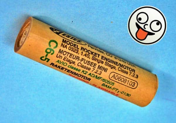
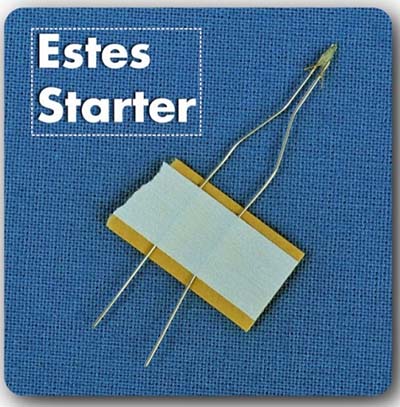
The model rocket igniter or electric match (see below), which is electrically initiated to ignite the black powder or composite propellant, is no different than any other piece of wire as it possesses electrical resistance (a measure of the wire’s ability to impede the flow of electric current). The igniter however represents the weak electrical link in the current path, its ampacity being considerably less than the other components in the launch controller circuit, and so functions as a fuse to initiate the burning of the propellant.
That’s to say, when the igniter is subjected to an appropriate electric current, its purpose is to generate sufficient heat so that the ignition temperature of the rocket motor propellant is reached quickly, thereby igniting the motor leading to a successful launch event. A model rocket igniter usually has a resistance of 0.5 to 2Ω, and it might work well with 6 to 12VDC. To be reliable, the igniter must stay hot enough (and long enough) to ensure that the motor propellant ignites decently.
In some launch controller circuit designs, the igniter is placed so as to present a short circuit to the source battery once the launch button is closed. In other designs, the igniter is placed in series with active drive elements which control the delivery of current to the ignition path. As you might already noticed, the latter method is employed in this launch controller design.
In order to finally initiate the launch process, you need to push and hold the launch button for a while, and then you can see the launching indicator alive. This time a little delay is introduced by the launch timer wired around the 555 chip (IC1), and the igniter is fired through the “normally-open” (N/O) contacts of the electromagnetic relay (K1) instantly after that delay period. The delay period can be changed by tweaking the RC network (R4-C5). Further, an active piezo-beeper can be plugged into the “beeper” connector to get an aural launching alert (warning horn) as it might be useful in certain situations.
Model Rocket Kits & Parts Store (India) https://www.rocketeers.in/shop/
Model Rocketry Guide https://www.electronicsforu.com/technology-trends/must-read/guide-model-rocket
Construction & Quick Test Pointers
A model rocket launch controller should be durable, safe, functional, and attractive in all respects. So, nothing is cheap and this project calls for many high-quality/heavy-duty components above and beyond that needed for a funny hobby electronics project!
You’ll need to build this circuit on Veroboard or some other form of the prototyping circuit board. All power wiring must be done with #18 stranded wire and all connections must be soldered for continuity and reliability. Also, make sure that the electromagnetic relay you choose can happily handle the heavy current flow to the ignitor.
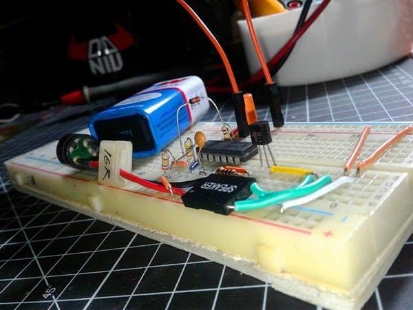
Nevertheless, it’s (as always) best to breadboard the circuit before actually making it. The use of different components may result in the circuit operating a bit differently, and you may find a few changes need to be made to get the circuit working in a faultless way.
The launch controller certainly needs a rechargeable battery, although this does not have to be mentioned yet. You can use either a 12V/7Ah SLA battery or a mighty 4S Li-ion or LiPo battery pack as the power source. This naturally calls for a compatible internal or external battery charger – you can of course go for a readymade one or a homemade one as desired.
It’s better if you make the launch controller an entirely self-contained portable device housed in a rigid and waterproof project box. A pair of female banana clips can be mounted on the enclosure as well to attach the ignition cable going to the launch platform. A 50-foot spool of 18 AWG stranded speaker wire with male banana clips on one end and spliced alligator clips on the other end will provide a gentle link to almost all types of model rocket engine/motor igniters.
However, the resistance of the long wires burns a significant amount of energy in the wire itself, instead of the igniter. A viable solution is to install the launch controller box near the launchpad while keeping the launch button remotely through low-voltage cabling. If so, only the short-length igniter cable needs to be heavy-duty, as the ignition power won’t travel all the way to the rocketeer with the launch button panel. The keylock switch in the launch controller certainly gives extra safety as it will help to disable remote launch operation when someone is working near the launchpad.
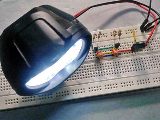
Finally, with a 12V automotive bulb inserted in the place of the igniter, you can test the operation of your launch controller at ease, verifying the entire sequence of powering up, arming, launch delay/countdown, and the simulated launch (say thanks to your burning light bulb)!
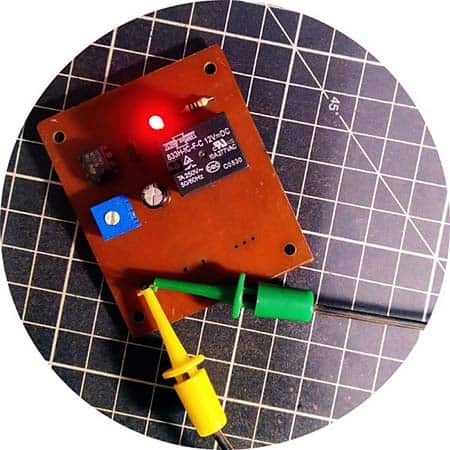
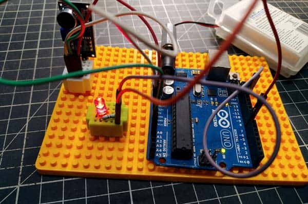
As an aside, I built the delayed launch controller – 555 IC circuitry – of this project as a standalone electronics on my home-brewed PCB and used a 100K trimpot in lieu of the timing resistor (R4) just for further experiments. Below you can see that circuit board (with some components soldered underneath).
Going Further…
This project is actually a mere revision of another project published by me before some years (https://www.electroschematics.com/model-rocket-launch-controller/). I am currently active in the design and development of an advanced model rocket launch controller project that offers a number of useful features and added security – albeit a slightly luxurious concept. More to come…stay tuned and keep asking questions!
Credits & References
Have any updates on the new controller?
Dylan Roll: Sequels to most projects are ridiculously late and I regret that. In my experience, the main reason behind this is some shipping issues between China and India (I’m in Kerala) since the Covid era. So I’ve to wait a long time to collect the required components. Anyway hopefully in the coming year I will be able to post all the pending projects one by one.
Thank you for your interest and reminder!