If you’re an audiophile, often you have to purchase rotary audio input selector switches for your home audio projects. You can of course buy such selector switches and selector switch modules via usual online channels for a little money but that’s not very easy at certain times.
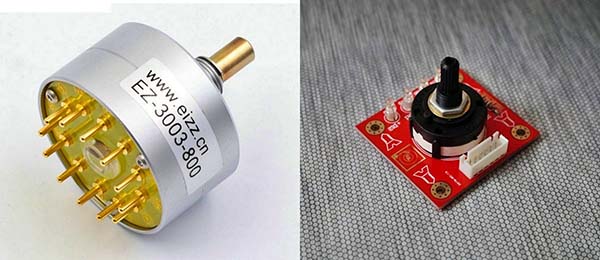
An audio source selector switch is pretty useful when you want to select between multiple audio signal inputs and route them to a single audio output, or one audio input source to many outputs. Nowadays, reasonably priced hobby kits for building your own multichannel audio input selector modules are also available through many online retailers. I’m not going to talk more about this – there’s always Google!
This article is not intended to describe the construction project of an audio signal source selector system, but only to show the simple idea of designing an electronic signal selector switch module within a limited budget. Hope you understand now!
Okay, let’s start with the basic schematic of the electronic signal selector switch module. As clearly depicted in the schematic, this design is based on a far-famed quad single-pole single-through (SPST) bilateral analog switch – the HEF4016B (IC1). Although the module is configured for 5V operation, it can be powered with dc voltages from 5 to 12 volts.
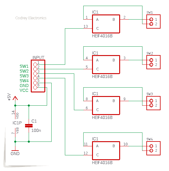
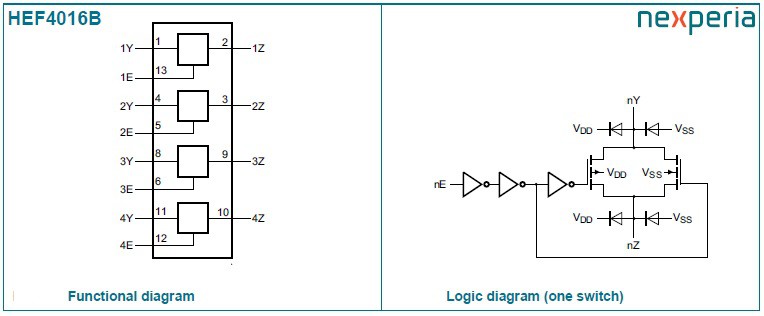
The HEF4016B provides four single-pole, single-throw analog switch functions. Each switch has two input/output terminals and an active HIGH enable input. When enable input is LOW, the analog switch is turned off. Below figure shows the functional and logic diagrams of HEF4016B (https://assets.nexperia.com/documents/data-sheet/HEF4016B.pdf).
That’s enough – let’s put it to work now. Below you can find an Arduino code tailored specially to test the HEF4016B module.
/*
  * HEF4016B Electronic Signal Selector Switch Module
  * Arduino Uno Test Code v1
  * Prepared by T.K.Hareendran / 04.2021
*/

int switchCount = 4; // Switch/Channel x4
int channel[] = {13, 5, 6, 12}; // Arduino Digital Pins x4
int halt = 3000; // Transition Delay (ms)

void setup() {
  for (int i = 0; i < switchCount; i = i + 1) {
    pinMode(channel[i], OUTPUT);
  }
}

void loop() {
  for (int i = 0; i < switchCount; i = i + 1) {
    digitalWrite(channel[i], HIGH); // Switch ON
    delay(halt);
    digitalWrite(channel[i], LOW); // Switch OFF
    delay(halt);
  }
}
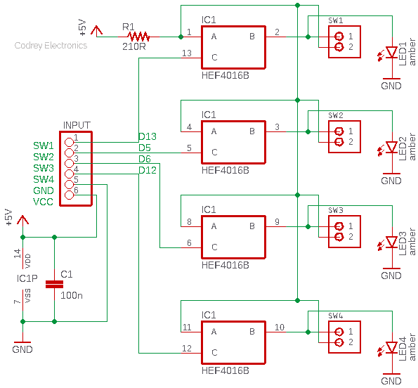
This simple code generates a sequential control signal to drive four LEDs wired directly to the four bilateral switches as shown in the following schematic.
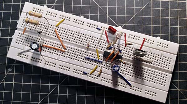
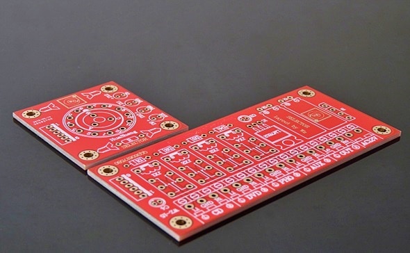
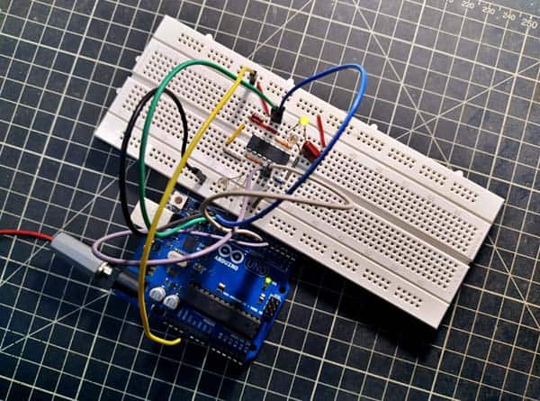
This is my quick test setup with components laid out on a standard breadboard:
So, now you’ve the circuit of an analog signal selector switch module contains four analog bilateral switches, each with active-high switch input and a bidirectional switch. When the switch input is asserted High, the bilateral switch terminals are connected by a low impedance path (switch state = on). When the switch input is Low, there is a high impedance between the switch 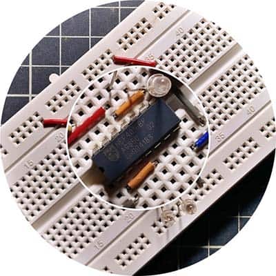 contacts (switch state = off). Note that the module can only handle a current of 10mA per switch/channel. Besides, each switch/channel has a substantial on-resistance which varies in accordance with the applied Vcc.
Once the working is verified, you can use your HEF4016B (or CD4016B) module independently or coupled with some other audio/video signal switching/multiplexing/gating projects. Be prepared to do some experiments with the High-Speed CMOS Logic Quad Bilateral Switch CD74HC4016 (https://www.ti.com/lit/ds/symlink/cd74hc4016.pdf) as well.
Notice my words, another better alternative here is the 4066 (CD/HEF/74HC….), because it is not only pin-compatible with 4016 but also has a significantly lower on-impedance and more consistent on-resistance over the full range of Vcc. I’ll try to describe more about this in a subsequent post.
As always, thank you for reading and I look forward to your comments and so on. Well, have fun, and make something fabulous!