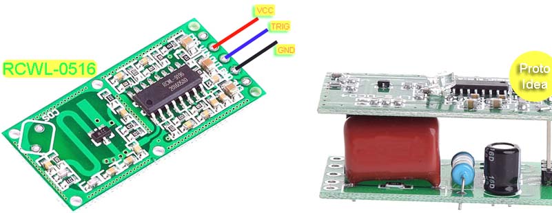
On certain occasions it is necessary to use a sensor module that generates a relatively short pulse to indicate a change of status. If the duration of its output signal is too short, the associated signal processing circuitry may not have enough time to capture the pulse and respond appropriately. A pragmatic solution is to extend the duration of the pulse to give the signal processing circuitry time to sense the signal. The universal pulse extender presented here do just that!
This pretty simple ‘hobby-grade’ design uses the iconic NE555 timer IC to sense the input pulse and generate an output pulse that can last for some moments. The entire circuitry can be powered from any regulated 5VDC power supply.
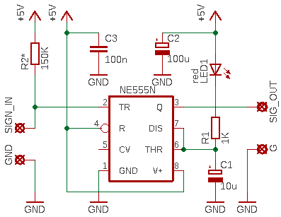
The duration of the output pulse mainly depends on the choice of resistor R1 and capacitor C1. The R-C values shown in the schematic are empirically chosen to handle the analog output signal provided by most Chinese sensor modules (for example, a piezoelectric vibration sensor module).
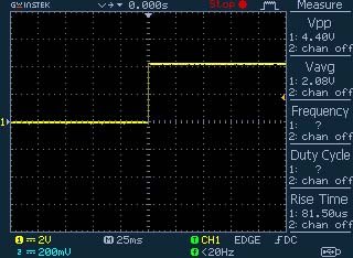
So, it takes a narrow 5V TTL level negative going pulse (SIGN_IN) and generates a wider pulse on the output (SIG_OUT). Here is what the output waveform looks like:
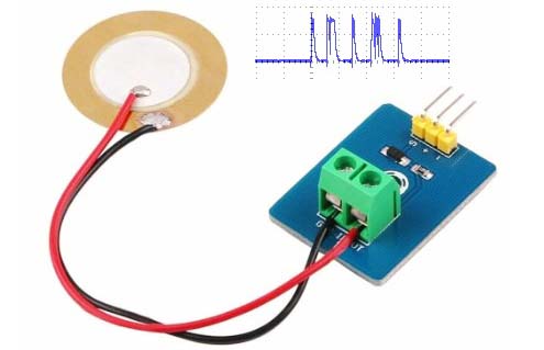
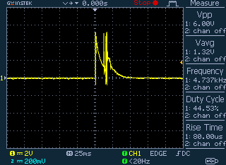
The input is actually the analog signal output (A0) of a quite common piezoelectric shock/tap/vibration sensor switch module (see the random scope trace below).
I have done this in multiple modules to modify the analog signal output whether the pulses/bursts are long or short. A recent case (as pointed above) is a cheapo piezoelectric shock/tap/vibration sensor switch module (https://www.xcluma.com/piezoelectric-shock-tap-sensor-vibration-switch-module-piezoelectric).
Well, let me close this little post, but after mentioning a few more things you should consider.
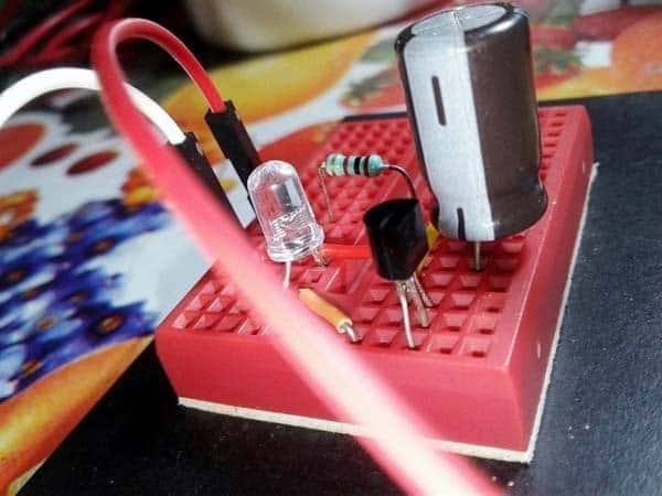
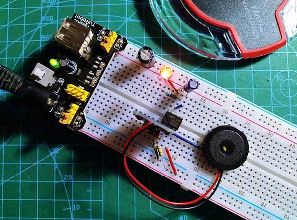
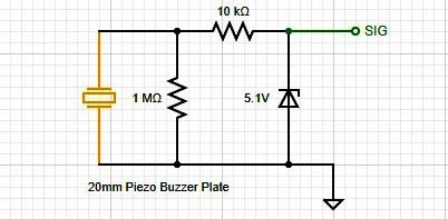
First, the design presented here can easily be modified as a standalone piezo shock/impact sensor module by adding the simple front-end circuit shown below. Hopefully this does not need much explanation.
Next, note at this point that the NE555 IC does create certain noise on the power supply rails, most applications can however live with this unwanted characteristic. Although this only applies to certain chips, it is always wise to use a 100uF electrolytic capacitor between the positive supply rail and ground rail as well as a 10uF tantalum capacitor and a 100nF ceramic disc capacitor just to on the side of forethought.
Finally, the maths of any design looks fine on paper, however, the end results once built are not always what you desired and will need further tweaking to get your circuit to operate exactly as you was after, largely due to component tolerances and deportment in a circuit.
Have Fun!