USB Power Bank – popularly known as mobile phone emergency charger – is an ideal solution for powering small microcontroller based hobby projects. Even the cheapest power bank in the market has so many useful features like auto power off and over current/short circuit protection which make them a safe and compact power supply for everyday electronics experiments.
However, one minor disadvantage (not a design flaw) is that the device switches itself off if the output load isn’t drawing current above a minimum level (usually 100mA or so). Because of this auto shut off mechanism, it’s very hard to power most basic microcontroller projects from the power bank as there’s a possibility of an annoying power cycling (restart-restart-restart) activity. One effective resolution is the insertion of a low-value resistor across the USB power supply output (VCC & GND) lines as a dummy load. Usually, a 47-Ohm/1 Watt resistor (a 100mA dummy load) will do the job well.
For most of us, constantly connected 47-Ohm resistor across a 5V power supply rail will raise some fears and doubts as there’s a remote risk of magic smoke from the ‘burning’ load resistor. So I did some experiments and found that presence of the said load resistor only for a finite time will keep the power bank happy to run without any issues. Later, I rigged up an ‘active load’ with a few scrap laying around my workbench. Shown below is the tried and tested circuit diagram of my USB Power Bank Adapter (v1).
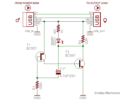
Parts List
T1: BC557
T2: BC547
R1: 100K ¼ w
R2: 22R ¼ w
R3: 1K ¼ w
C1: 4.7uF/25v
LED1: 5mm Green
Misc: USB ‘A’ Male plug, USB ‘A’ Female socket
My experimental setup was tested on my new “mI 10400 mAh” power bank and it worked great for me. If your fussy power bank still turns to sleep after a couple minutes, just try to replace the 4.7uF capacitor with a 2.2uF one as it looked very worthy with most power banks.
Note: Naturally, if you use your power bank for charging a phone or tablet it will work as intended, hence this external adapter is not necessary!
Hi there,
Thanks for the info, unfortunately i couldn’t get it to work with that configuration, the led blinked rapidly and the power bank still turned off, to resolve it I made the following changes
R1 changed to 50k
R2 removed – left open circuit
R3 changed to 220 ohm
device then worked on my power bank
Mick: Not to mention, there are countless power banks with pretty different internal circuits, so a successful hack on one model may not work on another. Anyway, glad to hear about your customizations and outcomes.
I had already planned to make a sequel to this article, but later I gave it up, because most USB-C power banks today have a “micro power” option to run loads that require only feeble current.
Last but not least, thank you so much for taking the time to share your valuable thoughts with other readers. Well, do what feels right for you. And when you feel ready, make it. Good Luck!