To use a capacitor in your electronic projects, understanding capacitor colour code is required. For identifying the capacitor values and tolerances international colour coding scheme (electronic colour coding) was introduced. Every capacitor has colors or alphanumeric characters on the body which indicates the nominal capacitance value of the capacitor. The capacitance can range from 1pico factor to 1 farad. To know the capacitance values of the capacitors we need to follow this steps:
How to Read Capacitor Values?
- Read the values or letters
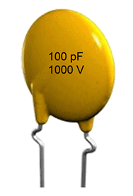
Every capacitor has a special marking printed on its body. It represents the value or colour code of capacitor. There are different types of capacitor and each has its specified capacitance value, voltage rating, temperature range, tolerance and life time. But most of the capacitors have their value and their voltage printed on their body.
- Look for voltage rating
The DC voltage rating of a capacitor plays a major role to determine how strong the capacitor insulation is. The voltage rating of capacitor tells the ability of the capacitor to withstand high or low voltages when applied across its terminals. This feature may help you not to burn up your circuit.
- Look for tolerance values
Tolerance of a capacitor shows the how much percentage the capacitance varies with respect to temperature. The tolerance value of capacitor ranges from ±0.1 pF to 10%. The best tolerance is the lowest percentage one. As the tolerance value increases the precision or rate of change of capacitance increases.
- Look for (+), (-) signs
The sign or marking (+ or -) tells the polarity of capacitor is positive or negative. Most of time leaded capacitor have + or -, while chip or ceramic capacitors having no marking. For this type of capacitors, we have to measure using an LCR meter. LCR meter can be used to measure inductance, capacitance and resistance.
Capacitor Colour Code Examples
- Ceramic Disc Capacitor
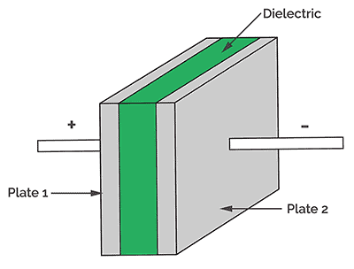
This capacitor uses ceramic as dielectric material (insulator). They are also known as multi layer chip capacitor (MLCC) or disc capacitor. The values for ceramic disc capacitors varies from 1 nano farad to 1000 micro farad. They are mostly used in electronic circuits due to their low inductance and resistance and better frequency response.
In disc capacitor or ceramic capacitor is shown below, there is a three digit number written on it.
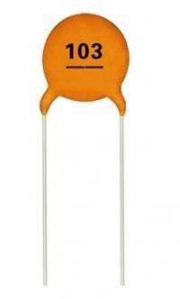
In this a 3 digit code 103 written on it. 3rd digit is a multiplier. So we should take 1st and 2nd digit and multiply with a 3rd digit which gives the capacitance value of the particular capacitor. Here is the example, 103k= 10 x103 which is 10000pF or 10nF or 0.01µF.
Let’s see one more example,
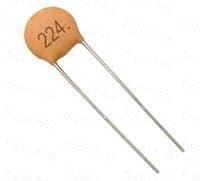
This capacitor has 224 written on it which gives the capacitance value of 22 x 104 = 220000pF or 220nF.
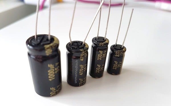
- Aluminium Electrolytic Capacitor
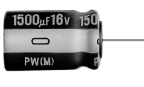
This type of electrolytic capacitor are made of aluminum used for power supply and switching DC circuits. The color code for this capacitor is written on the body as capacitance value and the voltage. This capacitors have low ESR values when compared with other group of capacitors.
- Surface Mount Ceramic Capacitor
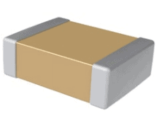
This type of capacitors are suitable cost saving and space saving purpose. These are available from pico farads to micro farad range. The dielectric is varied for different ceramics and hence the temperature and voltage rating is also different.
Capacitor Colour Code Table
Here is the different colors used on the capacitor, each colour has its digit, multiplier tolerance and temperature co-efficient. The colour code chart is given below:
| Color | Digit A | Digit B | Multiplier D | Tolerance T > 10pF | Tolerance T < 10pF | Temperature co-efficient |
|---|---|---|---|---|---|---|
| Black | 0 | 0 | ×1 | ±20% | ±2.0pF | |
| Brown | 1 | 1 | ×10 | ±1% | ±0.1pF | -33×10-6 |
| Red | 2 | 2 | ×100 | ±2% | ±0.25pF | -75×10-6 |
| Orange | 3 | 3 | ×1000 | ±3% | -150×10-6 | |
| Yellow | 4 | 4 | ×10000 | ±4% | -220×10-6 | |
| Green | 5 | 5 | ×100000 | ±5% | ±0.5pF | -330×10-6 |
| Blue | 6 | 6 | ×1000000 | -470×10-6 | ||
| Violet | 7 | 7 | -750×10-6 | |||
| Grey | 8 | 8 | ×0.01 | ±80%, -20% | ||
| White | 9 | 9 | ×0.1 | ±10% | ±1.0pF | |
| Gold | ×0.1 | ±5% | ||||
| Silver | ×0.01 | ±10% |
The following table shows the working voltage depends upon the capacitor:
| Color | Voltage Rating | ||||
|---|---|---|---|---|---|
| Type J | Type K | Type L | Type M | Type N | |
| Black | 4 | 100 | 10 | 10 | |
| Brown | 6 | 200 | 100 | 1.6 | |
| Red | 10 | 300 | 250 | 4 | 35 |
| Orange | 15 | 400 | 40 | ||
| Yellow | 20 | 500 | 400 | 6.3 | 6 |
| Green | 25 | 600 | 16 | 15 | |
| Blue | 35 | 700 | 630 | 20 | |
| Violet | 50 | 800 | |||
| Grey | 900 | 25 | 25 | ||
| White | 3 | 1000 | 2.5 | 3 | |
| Gold | 2000 | ||||
| Silver |
Here,
Type J – Dipped Tantalum Capacitors,
Type K – Mica Capacitors,
Type L – Polyester/Polystyrene Capacitors,
Type M – Electrolytic 4 Band Capacitors,
Type N – Electrolytic 3 Band Capacitors
In the code above A and B indicates 1st and 2nd digits and D is multiplier and T is tolerance. The last colour indicates the voltage rating. The working voltage is most important of all the characteristics. Working voltage is written on the capacitors which refers to the maximum voltage that can be applied across the capacitor. It refers the DC voltage. It is safe to operate the capacitor within its rated voltage. Otherwise, it may damage the capacitor.
Tolerance represents how much more or less you can expect capacitors actual capacitance to be from its rated capacitance which is printed on the capacitor. Tolerance rating is expressed as plus (+) or minus (-) value in ± Pico farads for low value capacitors which are less than 100pf or as percentage (± %) higher than 100pf for high value capacitors. It can range from -20% to +80% i.e. If a 100µF capacitor with a tolerance of ±20% can vary from 80µF to 120µF.
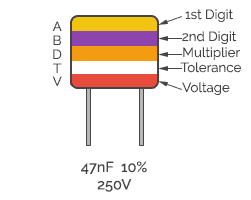
This five-band polyester capacitor can be read as 47nF from the above colour code with 10% of tolerance and 250V working voltage.
Conclusion
There are tens of capacitors (ceramic, aluminium, film, super, tantalum etc.) for the commercial grade, high voltage, high temperature, Aero space, Defense, RF and microwave, and power optimized applications. Each capacitor have colour code with own set of technical specifications. You have to choose the right one for your electronic application needs.
I have a small disc cap which just says “33” which is underlined.
Does that just mean 33 pF (no multiplier?)
Larrybud, yes if there are only two digits then the value is the same in pF. In your case, it’s 33 pF
Hello,
And for Surface Mount Ceramic Capacitor, how to know their value, pls ?
Thanks.