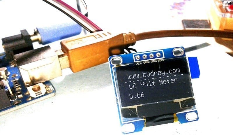
This article shows how to use an Arduino microcontroller (Uno/Nano) and an organic light emitting diode (OLED) display for making a basic digital voltmeter (DVM). The given design configuration makes it useful for measuring DC voltage up to 55V. The DVM can be powered from a 9V external DC source capable of catering a minimum output current close to 500mA.
Arduino Hardware Setup
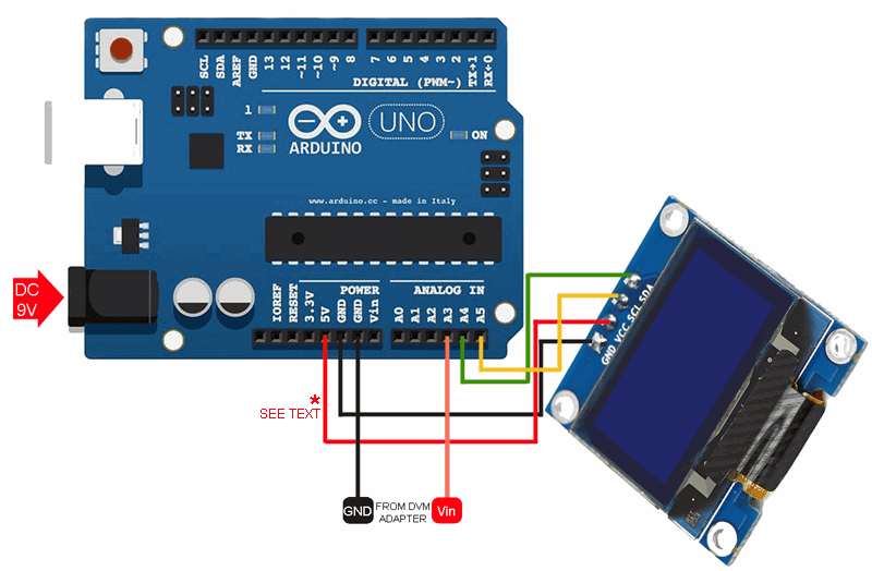
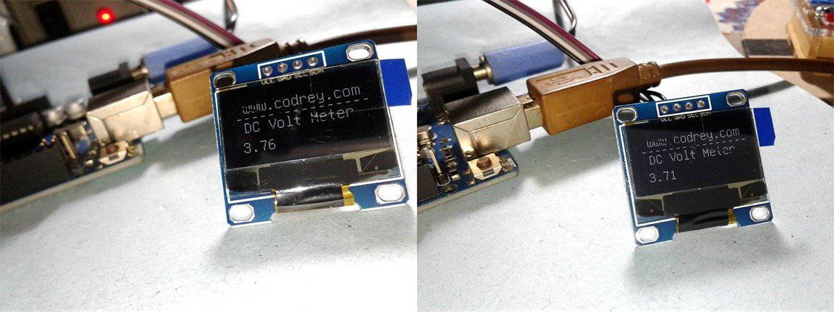
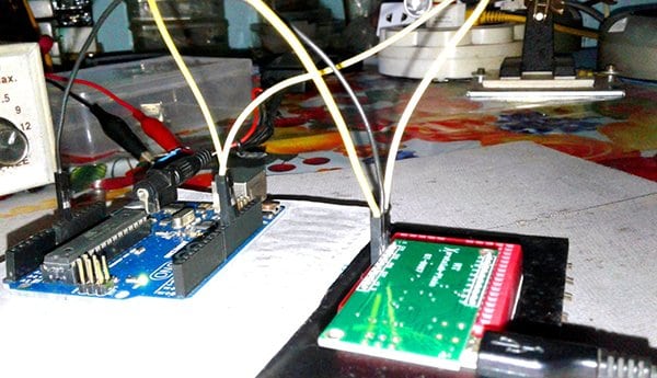
As you can see in the above figure, the Arduino hardware setup is fairly simple and straightforward. The 4-pin OLED display used here has an I2C interface in which data send/receive could be done serially through the SDA line. The OLED display (based on SSD1306 driver) is a 0.96’” type with 128×64 resolution, and is 5V tolerant. However note that there are different types of OLED display modules are available in market having different power supply needs, resolutions, communication protocols, etc. So first of all assure that you’ve the right OLED display in hand.
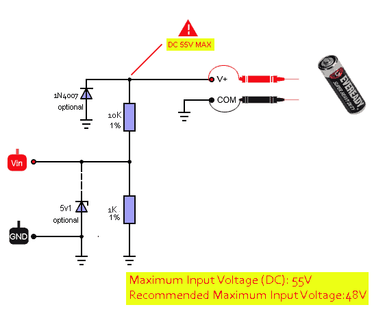
The DVM Adapter Circuit
As you are aware of Arduino’s analog inputs can be used to measure DC voltage between 0 and 5V (when using the standard 5V analog reference voltage). Here a digital voltmeter adapter circuit (simply a potential divider) is used to increase that capability up to 55V. The potential divider (1K-10K) sets the voltage being measured to within the range of the analog inputs. The potential divider divides the input voltage by 11, so with a 55V input the analog input will see just 5V. Although you can probe the DVM to 55V, it’s recommended highly to use it for measurement of voltages in 0-48V scale only. The diodes in the adapter circuit are optional circuit protection components thus can be omitted if you’re a confident player. Well, refer the DVM adapter circuit shown below.
Arduino Uno/Nano Sketch
Naturally Arduino range of microcontrollers provides analog inputs that can be used to measure voltage. The “analogRead()” function reads the voltage and converts it to a number between 0 and 1023. Further, the Arduino has its own voltage references and the default analog reference is5 volt on 5V Arduino boards. However accuracy of the said reference voltages is not very precise, and hence for precise voltage measurements you need to provide a more accurate external voltage reference (at present not very essential). For more details, refer http://arduino.cc/en/Reference/AnalogReference
/*
 * Arduinp OLED DVM
 * DC Voltmeter Range: 0-55V (see warning)!
 * Hardware: Arduino Uno R3 & 0.96" (128x64) I2C OLED (SSD1306)
 * Author: T.K.Hareendran/2019
 * Publisher: codrey.com
 */

#include <Wire.h> // Required Library 1
#include "U8glib.h" // Required Library 2

float voltageReference = 5.0;// Set Reference Voltage  (see notes)
float R1 = 10000; // VCC_Resistor of Potential Divider (10K)
float R2 = 1000; // GND_Resistor of Potential Divider (1K)

/* Connect A3 to the midpoint of the potential divider (see warning)! */

U8GLIB_SH1106_128X64 u8g(U8G_I2C_OPT_NONE);

void setup() {
}

void ReadVoltage(){

  float voltageInput = (analogRead(3) * voltageReference) / 1023.0;
  float Voltage = voltageInput / (R2 / (R1 + R2));
  if (voltageInput < 0.09) {
  Voltage = 0;

 }

  u8g.setFont(u8g_font_unifont);
  u8g.setPrintPos(0, 20);
  u8g.print(" codrey.com");
  u8g.setPrintPos(0, 30);
  u8g.print("----------------");
  u8g.setPrintPos(0, 40);
  u8g.print(" DC Volt Meter");
  u8g.setPrintPos(5, 60);
  u8g.print(Voltage);
  delay(10);

}

void loop() {

 u8g.firstPage();
  do {
    ReadVoltage();
  }while (u8g.nextPage());
  delay(30);

}
If the DVM reading didn’t match with that of your trusty precision lab multimeter then measure the value of the potential divider resistors and replace their values in the code with the exact values shown by your LCR meter/Multimeter. Besides, evaluate the voltage between 5V and GND headers of your Arduino board and substitute 5V in the code (float voltageReference = 5.0) with that accurate value (for example 4.94V).
OLED & I2C
Suppose your OLED display is a 3.3V type. Surely you can power it up with a regulated 3.3V DC supply available from the Arduino board or from an external power supply circuit. Since I2C bus of the common Arduino is still at 5V, is it cause a tragedy? Technically yes, but the devices on the I2C bus don’t actually drive the signals high, so the I2C allows for some flexibility in connecting devices with different I/O voltages. In general, in a system where one device is at a higher voltage than another, it may be possible to interface the two devices via I2C without a logic level shifter in between them. The trick is to connect the pull-up resistors to the lower of the two voltages. This only works in certain situations where the lower of the two system voltages exceeds the high-level input voltage of the higher voltage system – for example, a 5V Arduino and a 3.3V OLED.
So far as I remember there are no hard-wired pull-up resistors for the I2C bus of Arduino Uno/Nano (I can’t find them on the official schematic). Even though the internal pull-up resistors (20K-50K) are enabled in the library, they are not good enough here to make the I2C work. Nevertheless you won’t need to add pull-up resistors in the I2C bus between the Arduino and OLED display because even the cheapest I2C OLED display module available now has the requisite I2C pull-up resistors (1oK x2) onboard.
& Some tidbits
- My good old Arduino DVM Project – https://www.electroschematics.com/9351/arduino-digital-voltmeter/
- More details on SSD1306 OLED display – https://www.electronicwings.com/sensors-modules/ssd1306-oled-display
- Precision voltage measurement & Arduino – http://www.skillbank.co.uk/arduino/measure.htm
- OLED I2C Address & More – https://www.electroschematics.com/13294/open-source-light-meter/


SSD1306 & SH1106 – An Addendum!
Nowadays you can buy cheap OLED displays from many online sellers like a shot. However most are coming often with an unclear description SSD1306/ SH1106. Since the SH1106 OLED controller has an internal RAM of 132×64 pixel, while the SSD1306 has 128×64 pixel, there’s a possibility of a display initialization/memory mapping error.
In order to use an OLED display with unknown driver, try
“U8GLIB_SH1106_128X64 u8g(U8G_I2C_OPT_NONE);” or “U8GLIB_SSD1306_128X64 u8g(U8G_I2C_OPT_NONE);” in the ” // setup u8g object” of the proposed code, and check final results. Feel free to share your experience here!