This is the concluding part of the LED strobe article published last year (https://www.codrey.com/electronic-circuits/led-strobe-primer-part-1/).
During this long period (sorry for the inadvertent delay) I have already shared several strobe light ideas. But the sequel to the first post seems to be much awaited by regular readers. So, let me start again with some new ideas.
This time, the main focus is on the power LED driver circuit concepts, because a powerful strobe light requires a very strong light source. If so, you can easily build a tactical torch or similar light weapon too!
High-Power COB LED
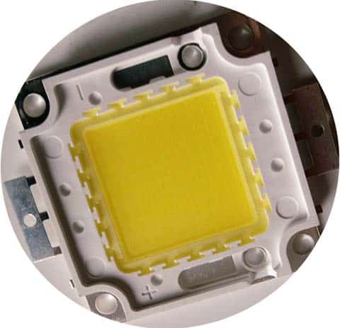
As mentioned before, an LED strobe certainly needs a powerful LED light source for most common applications. In the above figure, what you see is a cool-white 50W COB LED module once I got it from a Chinese online store. The COB (Chip On Board) simply denotes that this module has a number of LED chips in one package as a single module. Quick specifications of this particular LED module are listed below:
- Power: 50W
- Working voltage: 30-36V
- Current: 1500mA +/- 5%
- Brightness: 4700lm
- Colour: Cool White
- Dimensions: 52mm x 40mm
I did a quick test of this LED module with a constant-current switch mode power supply (1400mA @ 35V) and got cheerful results. Similar COB LED modules should be energized with constant current source because the voltage drop across a diode changes with its temperature, which if powered from a voltage source would result in a change in current as it heats up, which could eventually destroy it.
Keep note that efficient cooling is very essential for this LED module, even if you want to operate it only for a moment. It shouldn’t be turned on without a proper heat sink assembly at all. A CPU cooler mechanism from an old PC or Peltier freezer would work well for you – perhaps you may have one (or more) in your garret.
Moreover, be cautious, careless experiments with such a COB LED module may permanently damage your eyesight because the light source is dangerously strong!
High-Power LED Driver
High power LED driver means a DC power supply that is well-designed to power the LED in hand. It includes an additional ‘electronic switch’ to control the LED using an external circuit. This is required for almost all LED strobe projects (https://www.codrey.com/electronic-circuits/mighty-led-flashgun-v1/).
Since this is not final project idea, I would like to simplify this section by discussing a general design concept rather than a complex end-user circuit. I can clearly share a design that includes hard-to-find and pretty expensive components to achieve, but what fun is in it?
Probably, the easiest method for setting up a high-power LED power supply is to buy a readymade constant-voltage/constant current (CC/CV) buck-converter power supply module similar to the one shown below. It’s in fact a switching converter – linear regulators have the advantage of very clean output with little noise introduced into their dc output, but they can be much less efficient than switching converters especially when it comes to work together with high-power LEDs.
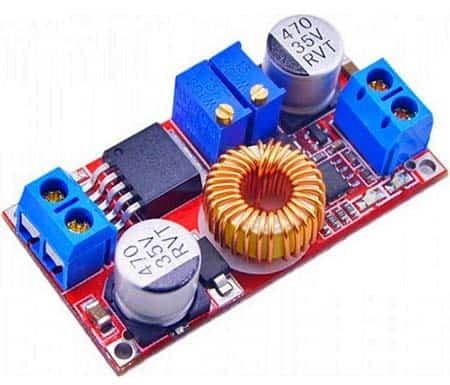
Here is a quick overview of the XL4015 IC based power supply module (http://www.xlsemi.com/datasheet/xl4015%20datasheet.pdf);
- Input Voltage Range: 4-38V
- Output Voltage Range: 2.5-36V continuously adjustable
- Output Current: Adjustable, up to 5A
- Output Power: Up to 75W
- Working Temperature: -40 ~ + 85 degrees
- Working Frequency: 180KHz
This is the link to a related article https://www.electroschematics.com/led/
This is a non-affiliated link to get the module online https://robu.in/product/5a-constant-current-voltage-led-drives-lithium-battery-charging-module/
After setting up your power supply module, all you have to do is attach an electronic switch as shown in the sample schematic below. At this point, note that in cases like this, a MOSFET is usually a better fit than a BJT.
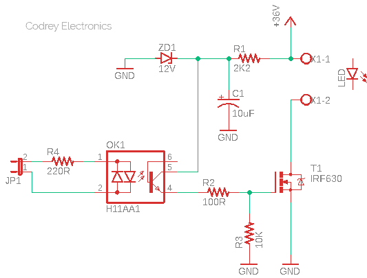
This is an isolated power driver circuit based on an ac optocoupler H11AA1 (OK1) designed to work with 36V (typical) dc power supply. You can of course configure this flexible circuitry to run on other dc power supply voltages simply by changing the value of the 2.2KΩ resistor (R1). Likewise, the IRF630 MOSFET (T1) is not a critical component – it’s okay to go for certain drop-in replacements. Finally, since the input element is an ac (bidirectional) optocoupler, it’s easy to trigger the driver either with a logic-high or logic-low output signal rendered by a 5V (or 3.3V) microcontroller. The 220Ω resistor (R4) limits the current flow through the LEDs housed inside the H11AA1 optocoupler. Resistance values up to 470Ω can be trialed here – the actual value depends on the current you want through the LED (this isn’t a complicated design process, but there’re a few important things to keep in mind when doing it – more on this later).
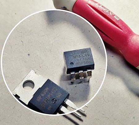
H11AA1 Datasheet: https://www.vishay.com/docs/83608/h11aa1.pdf
IRF63o Datasheet: https://www.vishay.com/docs/91031/sihf630p.pdf
Strobe Pulse Generator
The strobe pulse that drives the power LED driver can be a logic-level (high or low) signal which has a short on time and long off time. For example, a strobe pulse with 4ms on time and 54ms off time, thus a total cycle time around 17.2Hz with about 6.8% duty cycle.
The above timing values are never stringent, so many strobe codes on the web can help you make your own LED strobe. If you decide to code it yourself, be prepared to try out the following Arduino Sketch at the outset, as it may lead to some amazing ideas.
int strobeLED = 3; // D3 Strobe O/P
int val = 0;
int onTime = 0;
int offTime = 0;

void setup() {
  pinMode(strobeLED, OUTPUT);
}

void loop() {
  val = analogRead(0); // A0 Trimpot I/P
  onTime = val;
  offTime = (-2000000 / (onTime + 1000)) + 2000;
  onTime = onTime / 4;
  offTime = offTime / 4;
  if (onTime > 12) {
    digitalWrite(strobeLED, HIGH);
  }
  delay(onTime);
  if (onTime < 250) {
    digitalWrite(strobeLED, LOW);
  }
  delay(offTime);
}
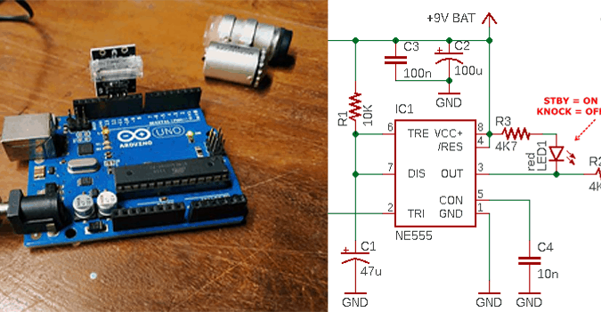
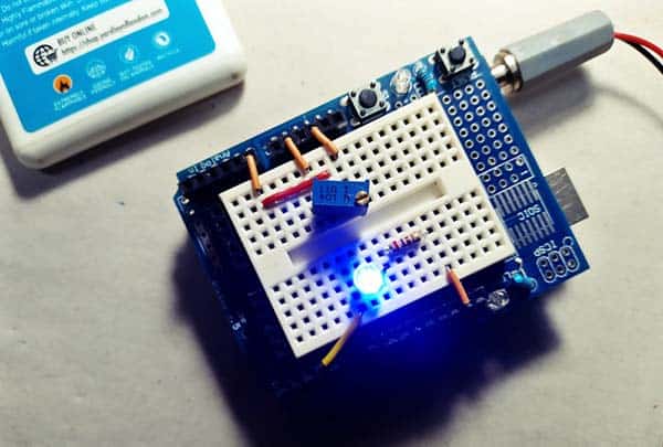
This is the Arduino hardware setup diagram. The blue LED in the setup is just a “debug” indicator which is optional. After initial testing of the Arduino setup, you should connect the D3 output to pin 2 of JP1 of the preassembled LED driver circuitry, and connect GND to its pin 1 (or vice versa – no problem).
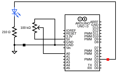
Note that the above presented experimental code (mere adaptation of a great code copied from web) provides a wide scale to control the strobe timing through the 100K trimpot i.e., from almost off (A0 = 0V) to almost steady (A0 = 5V). As it seems, the strobe pulse has a variable frequency up to around 25Hz, thence you will definitely get enough playground to run around. For my purposes, this range seemed about right.
Finale
Have you reached this far? Great!
If you’ve learned how an LED strobe light device (hardware and software) works, then this project is pretty simple to understand. A bit of fiddling with this can turn the setup into a useful stroboscopic tachometer, or a powerful light cannon at ease. This is not an overly detailed whitepaper but I’m happy to answer more questions if you’d like. Keep strobing 😊