Looking for a simple way to make your own automatic LED lamp for your staircases or corridors? This simple self-timing LED lamp gives you a defined light output at the exact time you need it.
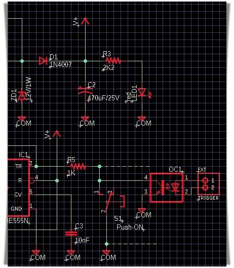
Getting it setup is easy! Below you can see the easy-to-follow schematic of the self-timing LED lamp (curious, yeh?).
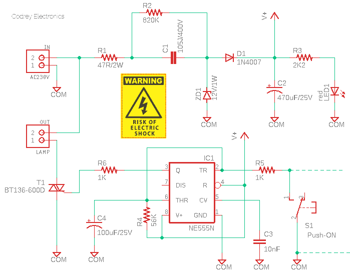
First part of the circuit is a crude AC230V to DC12V capacitive power supply (https://en.wikipedia.org/wiki/Capacitive_power_supply) realized with the help of a few easily available and inexpensive electronics components. In this transformerless low-current power supply, the voltage at the output will remain steady so long as the current out is less than the current in, which is limited by R1 and the reactance of C1.
Note that, R1 limits inrush current, and its value is chosen so that it does not dissipate too much power, yet is large enough to limit inrush current. Often, it may happen that, when switching off the circuit without load, C1 remains charged with the peak voltage of 325 V. It is then the task of R2 to discharge the capacitor as quickly as possible. The 12V zener diode (ZD1) operates as a voltage-limiting component while the 470uF polarized capacitor (C2) is responsible for smoothing the final output voltage. In addition, a 3mm red LED (LED1) is selected together with a 2K2 series resistor (R3) to provide a sensible power-on indication.
Next part of the circuit is a tricky timer built around the revered NE555N timer (IC1). An RC network (R4-C4) is used here to set the time constant which is close to 6 seconds, however, by selecting suitable values of R4 and/0r C4 you can set the desired time period. The output (Pin 3) of IC1 fires a BT136-600D sensitive-gate Triac (T1) that works as a solid-state switch to drive a (non-inductive) load of up to 4 Amperes when connected to AC230V.
- BT136-600D Datasheet https://www.mouser.in/datasheet/2/848/BT136-600D-1666873.pdf
Immediately after the circuit has been powered up, T1 gets fired by the output voltage available from Pin 3 of IC1 through the 1K resistor (R6), and this turns on the lamp connected with T1 for around 6 seconds. After that preset delay time, you can of course use the pushbutton switch (S1) to trigger the lamp over again.
At this point, note that, even though it might be possible to operate the triac in free air, in this case, it should be fixed to a heatsink or heat-dissipating bracket. The use of heat-transfer compound or sheet between the triac and ambient is also recommended.
- Triac Power & Thermal Calculations https://www.farnell.com/datasheets/1760767.pdf
In this circuit, T1 works as a dc-triggered power switch. When IC1 output is OFF, no current flows into the gate of T1 and the lamp is therefore OFF. When IC1 output is ON, gate current is applied to T1 from IC1 via R6 and T1 is driven into full conduction working like a closed switch, and full power is drawn by the lamp from the AC230V supply.
The 4Q Triac (4-quadrant triac) T1 can be controlled from a positive voltage supply using the simple gate resistor R6. The current will indeed flow through T1’s gate, provided by IC1 when its output pin is put on a high level. When IC1’s output pin is put on a low level, T1 is no more triggered.
- Triac Triggering & Gate Characteristics https://www.littelfuse.com/~/media/electronics_technical/application_notes/switching_thyristor/littelfuse_triggering_and_gate_characteristics_of_thyristors_application_note.pdf
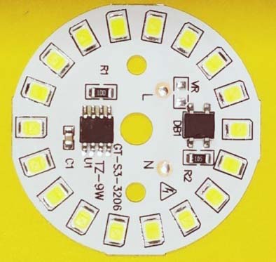
An AC230V (9W or so) DOB white LED plate is my choice for this applications as it’s a pretty compact piece of electronics, and has a cheerful power factor (https://www.electroschematics.com/linear-led-driver/).
Likewise, a doorbell switch is recommended for the trigger switch because it’s more safe, big enough, and easy to operate.

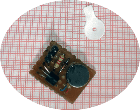
The circuit should be built on a small prototyping circuit board, it is best to use a socket for IC1. After successful construction, house the whole thing inside a plastic box as shown in the model enclosure sketch below.
Note that this circuit design allows you to wire multiple switches in parallel with the original trigger switch, allowing you to create multiple switch points for a single light. All you need for this is a number of doorbell switches and a long enough low-voltage two-core cable, just a little bit of skill and patience!
Furthermore, the inclusion of an optocoupler will allow you to control the lamp from another external/remote equipment, as shown in the circuit snip below (see OC1). This enables the lamp to work together with IoT devices, as well.
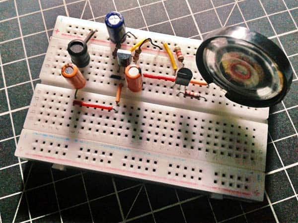
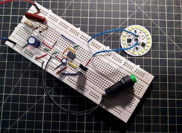
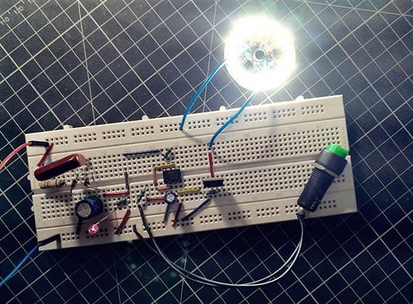
Following is a couple of casual snaps of my breadboarded test setup. Be cautious, Fatal AC230V!
Triac Quadrants? When triggering a triac we need to understand in which quadrants the triac will be operating, the theory may be a little daunting for newbies, though.
Nevertheless, it is good to simply recall that a triac does not have to operate in all four quadrants, nor does it travel through all the four quadrants for each AC cycle. In fact, for a given circuit a triac usually operates in only two quadrants, and operation in 2 quadrants is the bare minimum since we are working with AC (MT2 will be positive for one-half cycle and then negative with respect to MT1 in the next half cycle).
For instance, since the triac in this design is triggered with a continuous DC voltage, the triac will be operating either in quadrants 1 and 4 or in quadrants 2 and 3. This is because the gate current will always be either be positive with respect to MT1 (Q1 and Q4) or always negative (Q2 and Q3).
In other words, with continuous DC triggering, if the gate voltage with respect to MT1 is positive, the triac will be operating in Quadrants 1 and 4, and if the gate to MT1 voltage is always negative then triac will be working in Quadrants 2 and 3. That means, when the gate is sourcing current (trigger current flows from gate to MT1) then the triac is operating in Quadrants 1 and 4, and when the gate is sinking current (current flows the more positive MT1 to gate) then the triac is operating in Quadrants 2 and 3.
Below is a diagram showing all four quadrants (also referred to modes):
Finally, now that you have the simple and inexpensive design of a standalone self-timing lamp. The low-profile (and lightweight) circuitry is very easy to build and install. There are a few things that can be improved, but all in all you get a lot for your time and effort. Now it’s your turn. As always, be prepared and ready to do something fabulous!