I prepared this post in a hurry to help you to quickly design and build an analog audio visualizer using common light-emitting diodes. It’s not the first time I built a simple analog audio visualizer but if you found this post helpful, if you have suggestions, particularly if you found anomalies let me know.
What you see here is just meant to be a beginning – I hope so, at least. If I get plenty of feedback (that would be fine) I would like to add features people really need. Well, let me begin with the basic schematic of my analog audio visualizer!
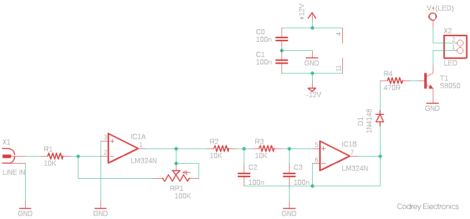
The basic idea here is to separate an input audio source into separate frequency bands. And then, depending on the amplitude of each band, light up an LED correspondingly. Thus, on a deep bass note, the low-frequency band caters to high amplitude, lighting up the corresponding LED brightly, while the other frequency bands have low amplitude and their LEDs do not light up. The trick lies in designing appropriate filters for different audio frequency bands to control the brightness of the LEDs.
In the above schematic, the LINE IN signal (X1) comes from an audio/music player. The first op-amp (IC1A) inside the LM324 (IC1) is a simple amplifier with an adjustable gain of about 1 to 6. The amplified music signal is then fed to the input of a Sallen-Key Filter (https://en.wikipedia.org/wiki/Sallen%E2%80%93Key_topology) wired around the second op-amp (IC1B). The Sallen-Key filter is a simple active filter based on op-amps stages, which is ideal for filtering audio frequencies. Note that, this circuitry demands a dual-polarity 12VDC power source (See notes included at the end of this post).
I deliberately decided to choose the Sallen-Key topology due to its overall simplicity and effectiveness as a second-order active filter. The IC1B here forms a low pass filter (LPF) with a cut-off frequency (fc) close to 160Hz (With 15KΩ resistors, you’ll get an fc of 106Hz).
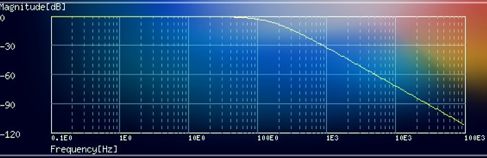
As you can see in the frequency response graph (see the bode diagram), the output of the Sallen-Key LPF is attenuated significantly as the input frequency increases from about 160Hz (The fc is actually 159.15Hz with a Q of 0.5).
Next reason to choose the Sallen-Key filter is that it’s easy on the op-amp. If your op-amp has a frequency range that goes as high as the cut-off frequency, you’re good to go. Note that the op-amp (IC1B in the schematic) is simply buffering the signal as it doesn’t have to manipulate any voltages in feedback to control anything. As pointed, I used garden-variety LM324 for this demo, and almost anything will work fine.
As a side note, I always like LM324 (https://www.onsemi.com/pdf/datasheet/lm324-d.pdf) because it’s cheap and works happily with input voltages as low as ground. But its poor crossover performance makes it inappropriate for quality audio projects. In particular, do not use LM324 (or LM358) for serious audio projects as their unbiased output stages create lots of cross-over distortions when the output current changes direction.
The amplified (IC1A) and filtered (IC1B) audio signal output available at the final stage of the circuit is then route to the base of the LED driver transistor S8050 (T1) after rectification by the 1N4148 diode (D1). The 470Ω base resistor (R4) limits how much current flows, and it’s amplified by T1 which modulates the current flowing through the LED(s). Although not shown in the scheme, the LED requires a suitable series resistor to limit its operating current (IF). Choose it wisely based on the voltage (V+ LED) used to drive the LED.
Oh, enough details for a little design, let’s go to build something practical!
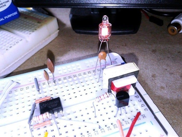
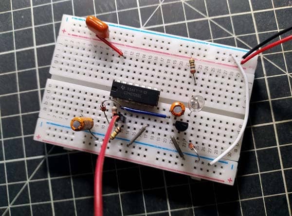
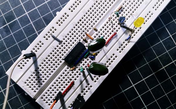
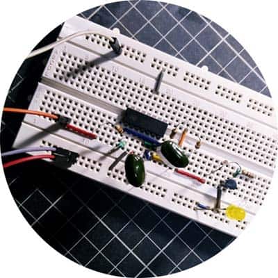
One of the painless ways to create a quick experimental setup is by using a standard breadboard. So, to summarise, I made my first version on a breadboard, yes, a little bit of a shoddy prototype built with junk parts I had on hand but it does work!
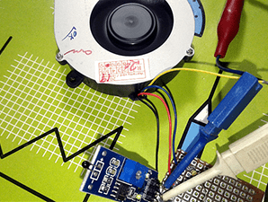
And then, I plugged my prototype into a few monoaural audio sources (-10dBV & + 4dBu) and did some quick tests. Everything worked out as expected, with a sensible response to the preset frequency scale. I also used the same setup to drive a small 12VDC SMD LED strip.
(-10dBV & +4dBu? https://huisr0t.wordpress.com/2014/02/25/10dbv-and-4dbu-voltage-levels/)
This is the casual snap of my breadboard assembly taken at the beginning of the experiment. Note, at that time I used a fixed 100KΩ resistor instead of a 100KΩ trimpot.
Obviously, you can add more filters because the LM324 is a quad-operational amplifier, and only two of them are employed here. The same idea can then be followed to create an active high pass filter (HPF), or an active bandpass filter (BPF) (https://wiki.analog.com/university/courses/electronics/electronics-lab-active-filter). It can be a perfect complement to the basic design. Give it a try
Until next time, thanks for following this post and making your way here till the end.
Addendum
As you’re aware, certain audio circuits demand both positive and negative voltages, which makes putting together a suitable power supply slightly trickier than it may at first seem.
See, when an audio signal generated by a circuit should have an amplitude of around 12V centered on the ground (-6V at the lowest point, +6V at the highest), the power supply needs to deliver voltages that are above ±6V.
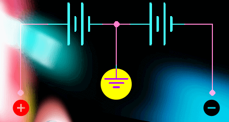
An “experimental” way to build a dual-power supply is by using two sets of batteries. The batteries are connected in series so that the positive terminal of the first battery is attached to the negative terminal of the second battery. When this middle connection is used as the ground reference for the circuit, you will be able to get a positive and negative voltage from the simplest setup.
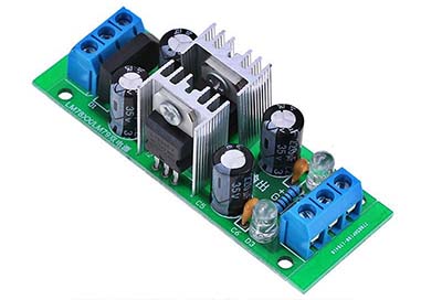
Anyway, if you don’t have the components to make your own dual polarity power supply from scratch, I would encourage you to get a pre-assembled module or a do-it-yourself kit of a dual voltage regulator instead (see below).