Sometimes ago I wrote an introduction to Raspberry Pi Pico. Today I will show how to exploit its pulse width modulation features. However, if you want to do some serious projects starting from this blog post, then I strongly recommend you do your own research on this topic to broaden your knowledge base. Okay, let’s get it started!
RPi Pico PWM
In this session, I will briefly talk about the RPi Pico PWM (pulse width modulation), and let’s see how to start making related projects with it.
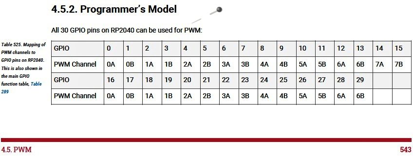
The RP2040 microcontroller at the core of the Raspberry Pi Pico has 8 Slices PWM, and each Slice is independent of the others. This simply means that we can set the frequency of a Slice without affecting the others. Luckily, there is a table in the RP2040 official datasheet (https://datasheets.raspberrypi.org/rp2040/rp2040-datasheet.pdf) to disclose which Slice/Output is associated with each pin.
As you can see in the datasheet, pulse width modulation is a scheme where a digital signal provides a smoothly varying average voltage. This is achieved with positive pulses of some controlled width, at regular intervals. The fraction of time spent high is known as the duty cycle. This may be used to approximate an analog output, or control switch-mode power electronics.
The RP2040 PWM block has 8 identical PWM slices, each with two output channels (A/B), where the B pin can also be used as an input for frequency and duty cycle measurement. That means each slice can drive two PWM output signals, or measure the frequency or duty cycle of an input signal. This gives a total of up to 16 controllable PWM outputs. All 30 GPIO pins can be driven by the PWM block.
An interesting thing at this moment to recall about PWM on the RP2040 is the possibility of having Duty Cycle values at 0% and at 100% without spurious peaks as happens on most other microcontrollers. Besides, it might be possible to have the two outputs of the same Slice with inverted phase signals (more on this shortly).
Look, there is a diagram in the official RPi Pico documentation (https://hackspace.raspberrypi.org/books/micropython-pico/pdf/download) to show the belonging of each pin of the Raspberry Pi Pico to the relative PWM channel. Below you will find that quick reference diagram.
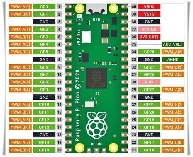
Here, the Slice number is depicted in square brackets on the orange labels. For example, pins 21/GP16 and 22/GP17 belong to the same slice – GP16 is output A and GP17 is output B. Also see the other two mirrored pins GP0 and GP1.
Pico PWM & MicroPython
Happily, handling Pico PWM in MicroPython is ridiculously simple and reduced to the bare minimum. The good news is that you can set both the duty cycle and frequency of PWM!
In order to use PWM in MicroPython, we will use just three trivial instructions:
from machine import Pin , PWM

pwm = PWM ( Pin ( 16 ) ) # GP16
pwm. freq ( 100000 ) # 100kHz
pwm. duty_u16 ( 32768 ) # duty 50% (65535/2)
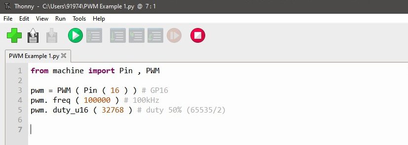
If you run the test code pointed above, in principle, it should generate a 100kHz PWM signal with a 50% duty cycle. My trusty oscilloscope, however, shows me about 99.92kHz with 49.94 duty cycle. This may be due to some inadequacies of MicroPython (correct me if I’m wrong)!
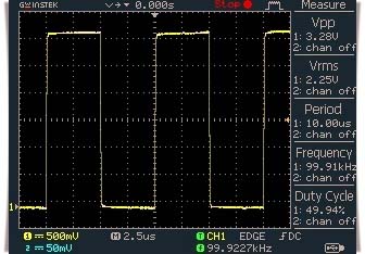
This is not a grievous issue in many situations. That means, we can still use this PWM signal to drive a DC motor or an LED as it works happily even if the drive frequency is slightly deviated from what it looks for. Anyway, I’m not going into the observed anomaly right now, but I will continue to investigate and post relevant updates here.
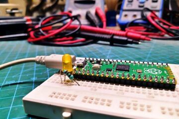
And on a side note, pulse width modulation allows you to gift analog deportments to digital devices, such as motors and lamps. This means that rather than the motor/lamp being simply on or off, you can regulate its speed/brightness. The following little code can be used to pulse a regular LED ( with 220Ω series resistor) wired to GPIO15 of RPi Pico dim and bright in a continuous cycle (courtesy https://projects.raspberrypi.org/).
from machine import Pin, PWM
from time import sleep

pwm = PWM(Pin(15))

pwm.freq(1000)

while True:
    for duty in range(65025):
    pwm.duty_u16(duty)
    sleep(0.0001)
  for duty in range(65025, 0, -1):
    pwm.duty_u16(duty)
    sleep(0.0001)
Wrapping Up
I started my play with RPi Pico a few months ago. But as a new toy for me, I am still trying to understand its secrets. So, if you spot a mistake, do not despise me. Instead, help me learn it properly.
Finally, you can certainly see more RP Pico projects in the coming weeks. If you liked this post or it’s useful to you, could you take a minute to go through other articles in this site where I have shared some ideas that might make you happy.
My trusty oscilloscope, however, shows me about 99.92kHz with 49.94 duty cycle.
That is the difference between the calibration on your oscilloscope and the absolute frequency of the crystal clock on the Pico. To get identical results would actually be very odd.
mIke: I appreciate you taking the time to share your thoughts. Thanks!
Thonny (python IDE I’m using for Pi Pico) flags a syntax error on line 10. It was actually caused by Line 9 having the wrong indent (4 spaces instead of 2), so that Line 10 and 11 will be inside the for loop.
Benjamin: You’ll get a syntax error if you have the wrong level of indent. Actually, I used four spaces of indent, but it seems like something went wrong while pasting it into the manuscript/webpage. BTW I’m sure you can easily indent those lines to make a valid code block. Thanks!
> it might be possible to have the two outputs of the same Slice with inverted phase signals (more on this shortly)
This is what I’m trying to hunt down at the moment. Did you happen to make any progress here?
Aaron D: Almost complete. I hope to be able to post the project here next month.
Thanks for the heads up!
Thanks for the info.
I’d like to use the onboard LED (GP25, not associated with any pin) to demonstrate PWM. Is there a way to associate by GPIO rather than pin? Particularly in CircuitPython (I have the Mu editor configured and working at this point).
@S Johnson: Thank You!
AFAIK Rpi Pico exposes 26 GPIOs from a total of 36 GPIOs available in the RP2040 uC. Out of those 26 pins, 23 pins are digital pins. These digital pins are marked as GP0, GP1, and up to GP22.
GP23, GP24, and GP25 are not exposed on the pinout, and hence cannot be used (GP26, GP27, and GP28 are the next available digital pins),
Anyway, have a look at this instructables https://www.instructables.com/Raspberry-Pi-Pico-Getting-Started-on-Board-Blink-L/
What I found to be odd is that yes, 65535 is the maximum duty cycle, the maximum integer that duty cycle can go is 68718 before rolling over to 0% duty cycle.
Joel Godin: Sorry I didn’t understand you. Please elaborate!