Circuit configuration of a Window Comparator usually consists of a pair of inverting and non-inverting voltage comparators in which the output indicates whether an input signal is within a voltage range defined by two different thresholds – the upper voltage threshold and the lower voltage threshold. The “window” then simply signifies the voltage levels between these two thresholds.
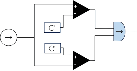
In this project, we are going to build a basic window comparator which is a very useful circuit even in the age of pretty cheap microcontrollers. This window comparator circuit employs two comparators, an input (sense) voltage and two fixed (reference) voltages.
The fixed voltages provide the upper and lower limits of acceptable value for the input voltage. If the input voltage strays outside these bounds, the comparator output will change, allowing it to raise an alert. Well, first let us see its well-annotated schematic diagram.
The key elements required to fulfil this little project are:
- IC1: MCP6002
- T1: 2SC1815
- D1-D2: 1N4148
- LED1: 3mm/5mA Yellow (or your choice)
- C1: 100nF
- C2: 1uF
- R1-R2-R3-R4-R6: 10KΩ ¼ w
- R5: 1KΩ ¼ w
As with any project, there are always improvements that can be made even when you feel it is okay at the moment. So, rather than jumping into soldering the components on a perfboard, first try to build it on a solderless breadboard because that will definitely assist further learning and experimenting at ease.
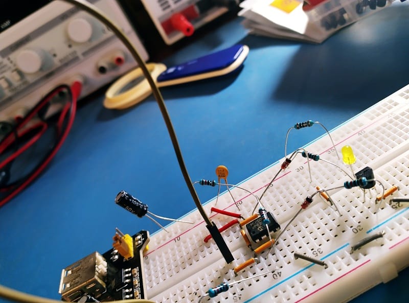
The basic circuit operation is as follows:
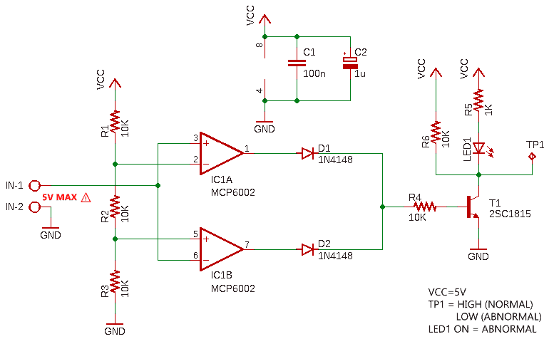
First off, take note at this point that this circuit is designed to run from a regulated 5VDC power source, despite some of the components being rated for relatively higher voltages (and currents).
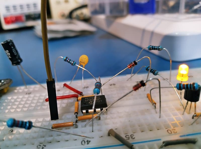
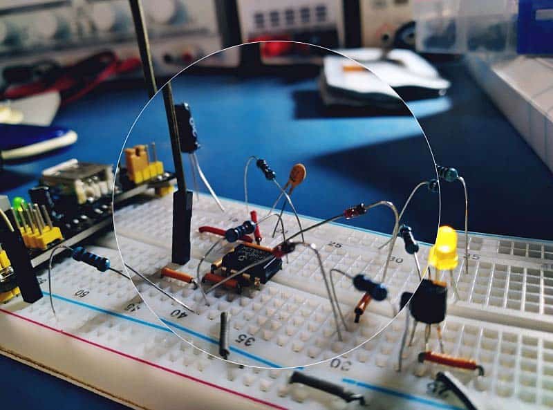
The MCP6002 (IC1) is a general purpose rail-to-rail low-power dual operational amplifier (op amp). However, considering that this is a comparator circuit, you could certainly use dedicated comparators instead.
As you can see, the circuit uses a voltage divider network, formed of three 10KΩ resistors R1-R2-R3. The voltage drops across each resistor will also be equal at one-third of the supply voltage (VCC). Therefore, the upper reference/threshold is set to 2/3VCC (3.33V) and the lower reference/threshold to 1/3VCC (1.66V).
So, when the input voltage (at IN-1) is below the lower threshold, which equates to 1/3VCC, output of the associated comparator will be high, and due to the positive voltage at base, the 2SC1815 transistor (T1) goes into saturation, thus turning the visual indicator (LED1) on.
Likewise, when the input voltage is above the upper threshold, which equates to 2/3VCC, output of the associated comparator will be high, and due to the positive voltage at base, T1 goes into saturation, thus turning LED1 on.
However, when the input voltage exceeds this 1/3VCC lower threshold and it is below 2/3VCC upper threshold, both comparator outputs will be low and the diodes are reverse-biased. So, no voltage is applied to the base of T1, and LED1 remains in off state. Not to mention, the output at test point TP1 is HIGH only when the input voltage is between the two thresholds.
Simply put, LED1 functions as an “abnormal input voltage” indicator ⚠
Note, while the comparator outputs are usually tied together to indicate an abnormal state, you can also use each comparator individually to know if the input voltage strayed too high or too low. Keep Experimenting…
Somewhat trivial but another thing to keep in mind is that the ultimate output voltage of IC1 is significantly lower than VCC due to the voltage drop introduced by the 1N4148 diodes (D1-D2) wired in logical-OR mode. You could of course mitigate this issue by using diodes with lower forward voltages, or you could use a CMOS two-input OR gate instead.
And as clearly pointed in the datasheet, the power supply pin (Pin 8) of the MCP6002 IC should have a local bypass capacitor (10nF-100nF) within 2mm for good high frequency performance. The VCC rail also needs a bulk capacitor (1 μF or larger) within 100mm to
provide large, slow currents. This bulk capacitor can be shared with nearby analog parts. Well, in this post we discoursed the design of a pleasant little window comparator circuit that, though basic, can potentially obviate the need for a microcontroller. A window comparator is an ideal way to monitor a safety critical sensor value, such as temperature or humidity.
A practical example of a window comparator application is a simple solar tracker circuit which will control two motors that move a solar panel to keep it facing towards the sun. Next up is an automatic over/under voltage protector. So, hopefully this is just a first part of a longer story. Stay tuned!