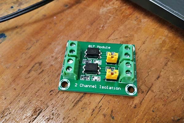
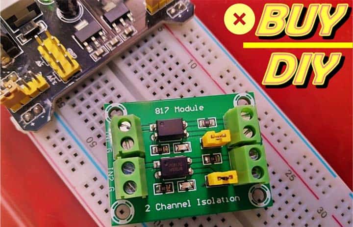
A while back, I came across a set of multichannel optocoupler modules at a discount sale, and what immediately caught my attention was the PC817 dual-channel optocoupler module in that collection. So, this post is about a quick analysis of the minuscule module. Is it a piece of electronics worth buying or not? We will see!
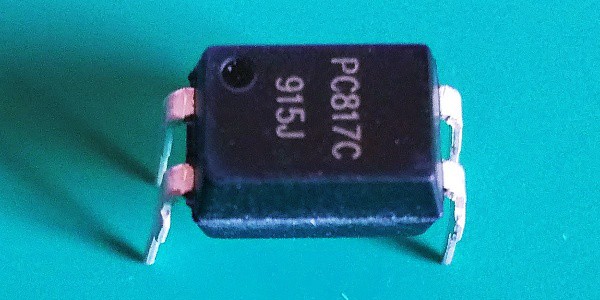
First off note that several other similar modules exist but in diverse shapes and configurations. All, however, are usually centered on the PC817C general purpose photocoupler.
This is the features/specifications of the module as provided by the seller:
- Product: PC817 2-Channel Optocoupler Isolation Module
- Input Port Voltage: 3.6V to 24V
- Output Port Voltage: 3.6V to 30V
As noticed, the module has four physical connection points. The screw terminals labelled IN1-G and IN2-G are input connection points, while V1-G and V2-G are output connection points. Besides there are two jumpers with removable caps to configure the ground (GND) rail, that means, the jumper enables the use of an external ground (jumper removed) or use the same ground (jumper installed) extended from the input.
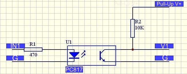
This is the circuit diagram of the module reverse-engineered by me. Only one channel schematic is given here as both channels are identical.
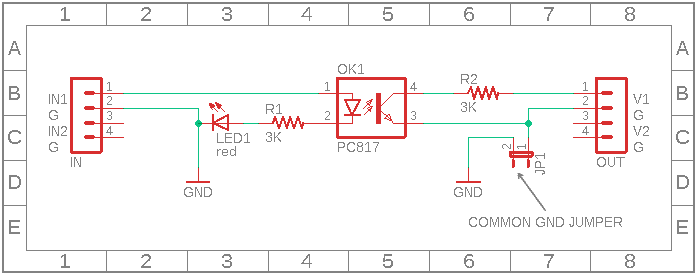
Call to mind, there is a jumper for each channel. If the jumper is connected, the G pins of input and output are linked up. But if the jumper is not connected, those pins are freestanding.
At a glance this module looks pretty useless as it seems to be a poorly designed module with a couple of design flaws. Let me dive into it now.
At first, using a 3KΩ resistor and a red LED in series with the input of the PC817 optocoupler seemed very strange (at least to me).
Just imagine that a microcontroller is on the input side of this module, and if the microcontroller’s I/O pin plugged into the input port of the module signals the optocoupler by sending just about 5V, is ample current available to lighting up the optocoupler’s internal LED?
I measured it. At 5V input, circa 1mA is the maximum current flow observed there!
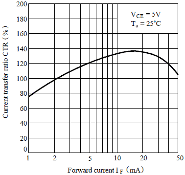
The graph in the below figure depicts the current transfer ratio (CTR) vs. forward current (IF) of the PC817C photocoupler. Take a deeper look at it now to see what goes on behind the scenes!
Second, the circuit will work, but it does not always seem practical to use the existing output interface as it is. As you can see, a 3KΩ resistor is wired in series with the collector/output terminal of the optocoupler. What is the logic behind this? In this current configuration, it does not act as a pull-up resistor. Strange!
In short, this is definitely not a microcontroller-compatible optocoupler module. This comment will be retracted if anyone proves it wrong. Frankly I prefer to use the circuit idea shown below for that, so you too can turn on your soldering iron to make a practicable optocoupler module yourself.
Note, next higher preferable value for resistor R1 is 1KΩ.
- Assuming 5V at the input point (IN1)
- The forward voltage (VF) across the infrared LED inside PC817 with a forward current of 4mA will be about 1.2V
- 5V − 1.2V = 3.8V to be developed across R1. Therefore R1 = 3.8V/4mA = 950Ω
- Rounded off to 1KΩ
Also,
- The CTR vs. IF graph of PC817 shows that ideally the CTR will be about 115% with a forward current of 4mA, which suggests that the output current should be about 4mA x 115% = 4.6mA
- To saturate the phototransistor at 5V pull-up and produce a logic-low at the output (V1), R2 must develop a voltage of 4.9V-5V when passing a current of 4.6mA
- So its value must be at least 5V/4.6mA = 1087Ω. That is R2 = 1.2KΩ (increasing this by a few KΩ could ensure that the output has the maximum voltage swing, but it might reduce the speed with which the optocoupler can respond to fast voltage changes)
Getting back to the dual-channel optocoupler module we are discussing, in my haste to snap up a discount sale deal, I failed to realize that it might have some downsides. So my advice is not to buy these (or similar) absurd optocoupler modules for microcontroller projects, as it is always better to make your own according to your individual needs.
Ultimately, after some extensive research, I discovered that this module is actually designed to drive power MOSFETs with or without galvanic-isolation (see below diagram). Maybe it was tailored on purpose for some industrial application, who knows!
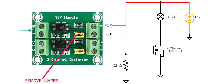

Thank you for the schematic and greetings from Brazil. For my application, an industrial process with 28V input and a programmable logic controller at the output, this design seems to meet my requirements.