This little post is to refresh your knowledge about the far-famed CD4066B CMOS Quad Bilateral Switch IC.
The CD4066B is a quad bilateral switch intended for the transmission or multiplexing of analog or digital signals. It consists of four bilateral switches, each with independent controls, and both the p and the n devices in a given switch are biased on or off simultaneously by the control signal. Below figure depicts its block diagram and pin configuration.
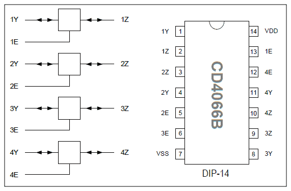
Here, 1Y and 1Z indicate analog input/output for switch 1 and 1E indicates enable (on/off) control for switch 1. Other switches follow the same Y-Z-E denotation pattern.
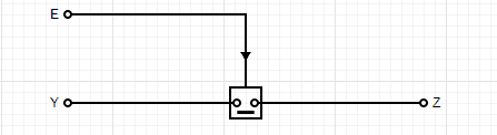
A LOW (L) input on the Enable pin (E) turns the corresponding analog switch OFF, while a HIGH (H) control input turns the same analog switch ON.
So, we have a quad bilateral switch, that is, four switches in one IC. With regards to the current the CD4066B chip can switch, the maximum is ±10mA per switch, which seems okay to run a low current LED or a typical logic gate (Correct me if I am wrong).
Recall at this point that the CD4066B IC has four independent digitally controlled analog switches. Each switch has different control pins which allows for more options for the outputs.
And, the IC has a large absolute maximum voltage for VDD of 20V.
The VDD pin of the CD4066B IC should have a good bypass capacitor to prevent power disturbance. The bypass capacitor (100nF ceramic capacitor recommended) should be installed as close to the power pin as possible for best results.
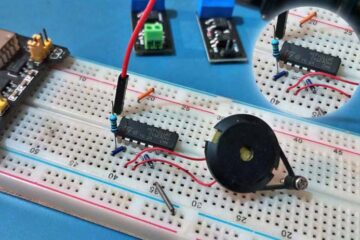
Talked enough – let us put it to work now with a quite simple demo setup!
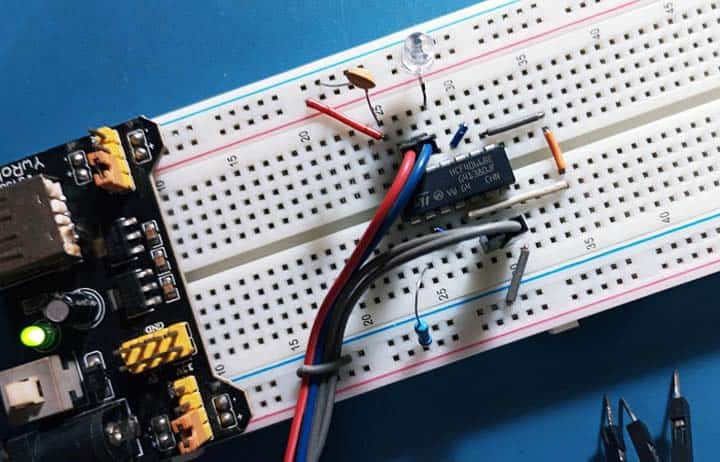
As can be seen in the below schematic, here the HCF4066BE (IC1) is wired as a 4-input AND gate. The IC contains 4 analog switches, which are all connected in series so that unless the inputs (A1-A4) are all HIGH, no voltage is applied to the visual indicator (LED1) connected at the AND gate output (TP1).
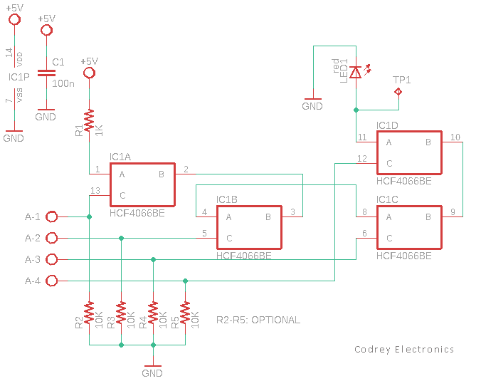
Although there is no particular need to employ an LED here, I added it just to see how the test setup works. You can of course replace it with a relay or similar load after adding an appropriate BJT as the driver component.
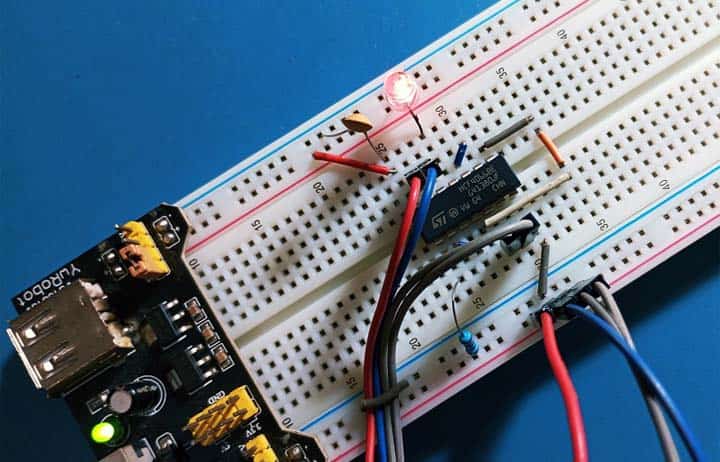
Well I hope you found this basic experiment interesting, and it can serve as the basis for several serious practical projects. Have Fun!