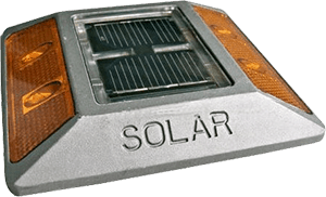
Let me start this month with a Solar LED Road Stud project. Solar LED road stud is a self-powered, autonomous device usually installed on the center line of a road, the lane boundary, and crosswalks to clearly guide drivers and pedestrians in nighttime, rainy or foggy weather. Solar LED road stud charges its rechargeable battery through a small built-in solar panel module during the daytime so that it can work as an effective safety marker in darkness.
The project is based on a cheap Chinese LED driver chip QX5252F in TO-94 package. Only one small inductor is needed here as an extra component to build the core part of the project!
List of Components
- IC1 – QX5252F (TO-94)
- LEDs –White (Generic 5mm)
- L1– 100uH/~100mA Inductor (Generic)
- SP – Solar Panel 2.5V/200mA (YT58X70)
- BAT –Ni-MH cell 1.2V/800mAh (Generic 2/3AA)
Circuit Diagram
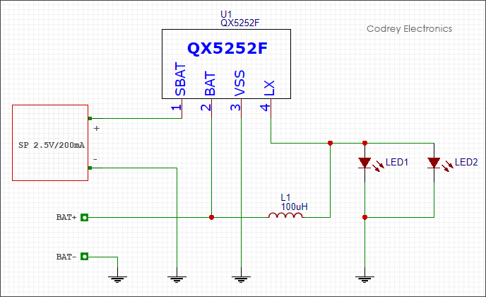
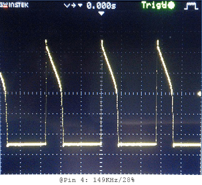
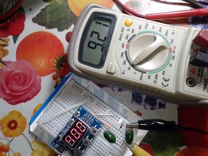
As seen in the circuit diagram, the given configuration is powerful enough to drive two white LEDs in parallel. In my breadboard prototype with only one LED, the configuration oscillates near 150KHz (see next image). Just be aware that if you alter the value of the inductor, the output current you’ll get will also be changed accordingly. For example, 47uH inductor in lieu of the 100uH will give almost two-fold output current (more than enough for driving two lamps). The white LEDs are used here deliberately so that with various transparent filter sheets you can change the color of light as desired, bright yellow or amber for instance.
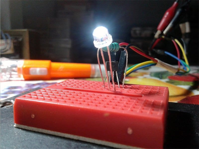
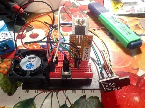
Now, here’s what my initial test setup looks like wired on the breadboard (without the solar panel).
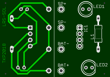
PCB Artwork & Construction Hints
Take note, image of the PCB artwork is not in actual size!
Obviously, this little device is designed to stay on the road so it needs to be waterproof and shock resistant. Aluminum alloy and UV Polycarbonate are good materials for making the enclosure. Recommended Waterproof Rating is IP6/8, Operating Temperature Range is: – 40degC to +80 degC, and the Compression Resistance is 18 MTs (Google these for more information). For waterproofing, I’ve used Silicon Sealant (DrFixit) to stick the solar panel on the top of the enclosure as it can prevent water flowing into the enclosure through the top lid. I followed the same practice while I was joining the side and the bottom sections.
I hope this article will help you designing your own solar road stud and you’ll have fun making it yourself.

Hello My name is James Ireland, and I was really surprised to find your site. I have tried many times to find a circuit for a solar road stud as I am trying to make one with 6 led’s 3 on each side of a circular road stud. I know I can simply buy one, but I am not going to learn the circuitry that way. Can you possibly help in this matter? I did find something on Electro Schematics but not with 6 led’s. Thank you James Ireland.
James: Thank you for your keen interest in my little design ideas.
As you may have noticed, we cannot drive six or more LEDs with the QX5252F chip. Anyway, I’ll be back here in a few weeks with the idea of a mighty solar road stud. At the same time, you may try to adapt this (a bit old) idea to your project http://ludens.cl/Electron/ledlamp/ledlamp.html
I’m very interested to see how your projects turn out. Please keep us up to date!