I volunteered to design a simple and inexpensive isolated power mosfet switch to control some electric loads by a ‘pulsed’ low-voltage input signal. There are of course superb solid state relays (SSRs) that we could easily interface to drive them from various input signals, but what’s of concern here’s to cook up one fairly cheap circuit without an opto-coupler, for certain reasons. Further, I was apprized that the proposed input signal will be a low-voltage square wave with its frequency lies in 1KHz – 10KHz scale, and the output switch must handle a minimum of 10A current at 12V DC. Affrighted for a while!
Beginning of the experiment
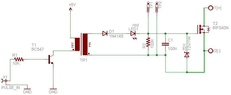
I’d already attempted audio output transformers for perfect galvanic-isolation in many designs, so naturally decided to rig up the isolated power switch circuit with one common 1300:8Ω audio output transformer I bought from Banggood. Following is the basic schematic drawing of that construct.
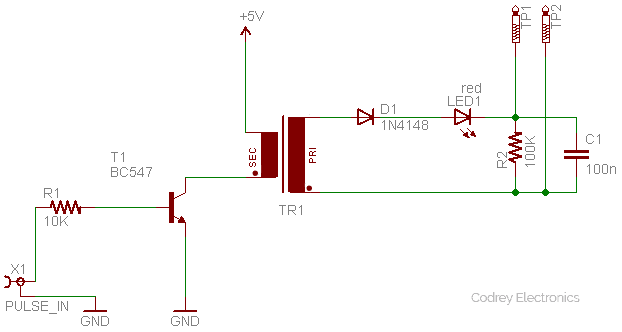
As you can see, the circuit is very simple and straight forward. Here, the audio output transformer (TR1) is used in reverse with a small-signal transistor (T1) wired to drive its secondary coil (8Ω impedance) by the input signal. The primary coil (1300Ω impedance) is routed to a half wave rectifier (D1) which will ‘theoretically’ top up a capacitor (C1) to the peak voltage of the incoming waveform so that when the input signal’s amplitude increases, the capacitor voltage is also increased, and when the input amplitude falls, the capacitor voltage is reduced by being discharged through a ‘bleeder’ resistor (R2).
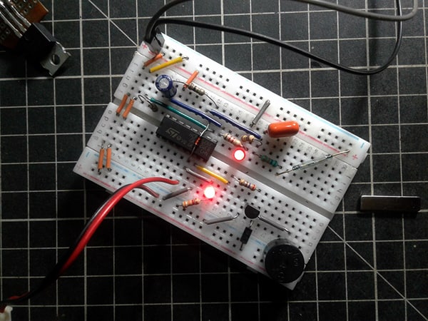
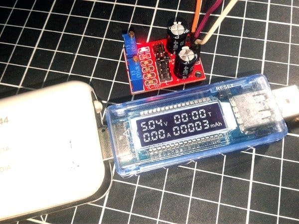
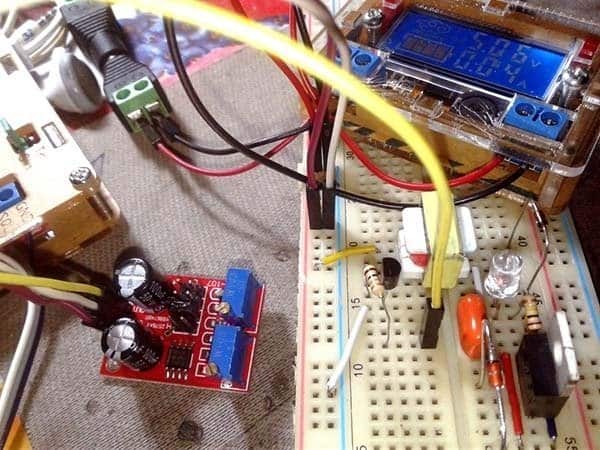
After successful construction of the circuit on a MB-102 breadboard, 1KHz (50%) square wave signal was applied to the 5V-powered input from a cheap 555 IC pulse generator module once I got from an eBay seller (see next image).
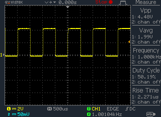
See the input wave from with a p-p voltage close to 4.5V
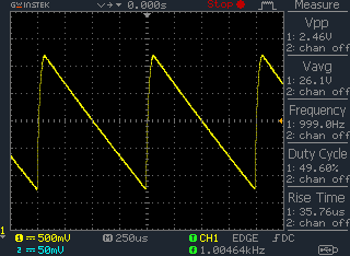
And, this is what I captured across the 100K resistor (R2). Aright?
Nailing down
Thereafter the design was completed by adding one power mosfet IRF540N (T2) as shown in the below schematic. The 12V/1W zener (15V/1W can also be used) sits down there to ensure effective gate protection for the power mosfet.
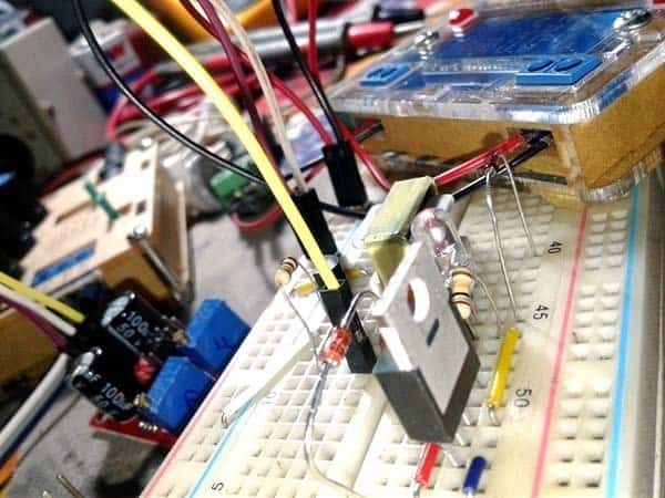
Also do take a look at my breadboard model.
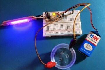
Eventually, the output load switching function was tested with a 12V-rated (but a low-current type as it’s only in hand at that time) green LED light strip with success (see next image).
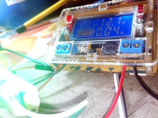
Although I started merely with the 1KHz square wave input, square wave input signals with frequencies beyond 10KHz was used to test the finished setup later but it worked!
Parts list
| R1 | 10K ¼ w |
| R2 | 100K ¼ w |
| C1 | 100nF/100v |
| D1 | 1N4148 |
| LED1 | Red/5mm |
| ZD1 | 12V/1w or 15V/1w |
| T1 | BC547B |
| T2 | IRF540N |
| TR1 | 1300:8Ω audio output transformer* |
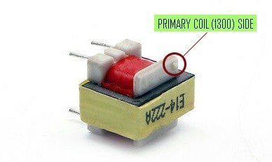
Getting back to the special component – the audio output transformer, note down that one of the main applications of audio frequency transformers is impedance matching in order to achieve maximum power transfer. The audio frequency output transformer works at frequencies between around 20Hz to 20KHz, and matches the high impedance output of the audio amplifier to low impedance of the loudspeaker.
You can learn much more about audio frequency (AF) transformers from here https://www.electronics-tutorials.ws/transformer/audio-transformer.html
And, you may go through this link to collect a batch of the requisite audio output transformers (1300:8Ω) https://www.banggood.in/10pcs-1300-8-Ohm-Audio-Transformer-EE14-Transformateur-Audio-POS-Transformador-p-1094073.html
Enough room to turnaround!
As you might observed, my concept resembles an ‘odd’ Solid State Relay for DC loads, and thus leaves enough room for expansion of the basic idea, indeed. To exemplify, just assume that you can get into the build of a low-voltage oscillator circuit ready to deliver proper drive pulse to the existing isolated power mosfet switch circuitry. If so, by integrating both will help you to switch high-voltage/high-power electric loads from a very low voltage dc power supply output too, certainly with decent galvanic-isolation (refer the block diagram shown below).
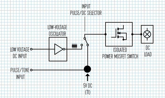
Concisely such a setup obviates the terrible requirement of a logic-level power mosfet (plus the isolation mechanism) when you need to drive an external electric load probably by a feeble signal that’s available from the I/O port of a standard microcontroller. The proposed enhancement is in progress, so don’t expect anything to be functional now. I will try to complete it within a couple of weeks and let you know how I get on. Stay tuned!
Addendum
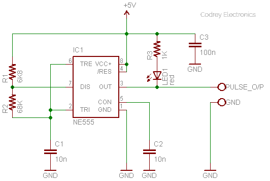
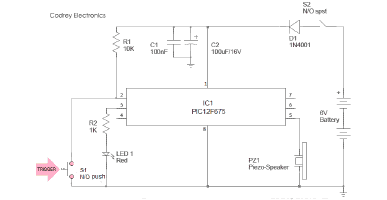
Following is the “textbook” circuit diagram of a do-it-yourself 555 IC based, 1KHz, near-symmetric, square wave generator which is quite useful for the experiments detailed in this article. Give it a good try to head off the ineluctable demand of an eBay pulse generator module!