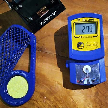
After getting my new soldering iron tip thermometer, I got inspired by that idea and decided to design a quick digital thermometer for general use. By the way, the soldering iron tip thermometer is an indispensable tool for electronics hobbyists, technicians, makers, etc. because they often have to check the tip temperature of different soldering irons. Okay, I will write a detailed post about soldering iron tip thermometers and share it here later.
So, I take this space to share the project details of my Quick OLED Thermometer. Get ready to try it out now!
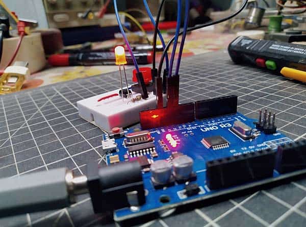
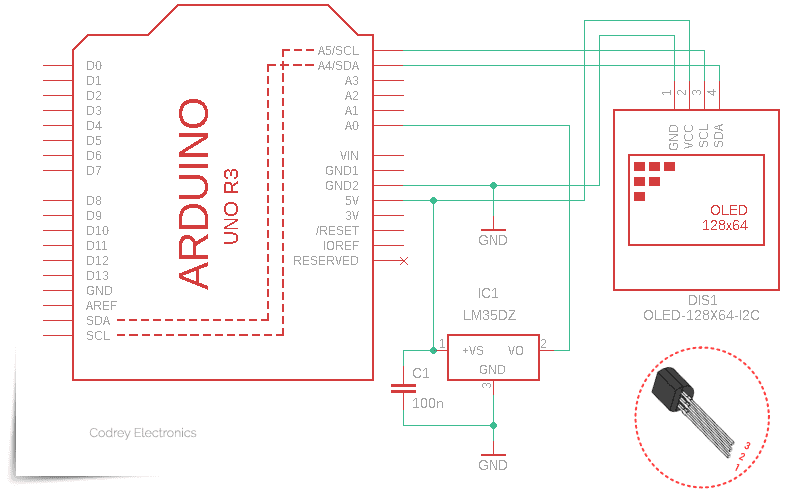
Here’s the hardware configuration scheme for my Arduino OLED Thermometer:
See the list of its key parts below.
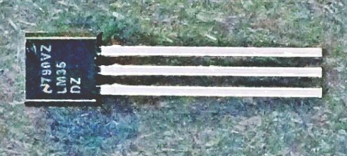
- LM35DZ Temperature Sensor x1
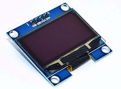
- 128×64 I2C OLED Display x1
- Arduino Uno R3 x1
- 6F22 9V (400mAh) Battery x1
- Arduino Uno ProtoShield (optional) x1
As you can see the hardware assembly is really simple. The VDD and GND pins of the 128×64 OLED display module are connected with the Arduino’s 5V and GND, while the SCK and SDA pins of the OLED display are connected with the Arduino’s Analog pins A5 and A4 which are the I2C pins (Serial Clock & Serial Data). The display is a mono-color, 0.96-inch with 128×64 pixels I2C OLED display module. Unlike the common 16×2 LCD module, this display does not require a backlight, which results in a very nice contrast and moreover, it consumes less power when compared with other displays. The default I2C address of the OLED module used here is 0x3C.
The familiar temperature sensor component LM35 hardly needs an in-depth explanation. It’s a precision 3-pin integrated-circuit temperature sensor with an output voltage linearly proportional to the Centigrade temperature (https://www.ti.com/lit/ds/symlink/lm35.pdf). Note that theLM35 has a very wide 4V to 30V power supply voltage range, and it’s recommended to add a 100nF capacitor from V+ to GND to bypass the power supply voltage in noisy surrounds.
The Arduino sketch (code) is very straightforward. Actually, I was able to borrow much of the code from my previous experiments for each of the parts I used. For this step, however, you need to already have the Adafruit_SSD1306 & GFX libraries downloaded and installed. So, open your Arduino IDE and go to Sketch > Include Library > Manage Libraries. The Library Manager should open. Type “SSD1306” in the search box and install the SSD1306 library from Adafruit. After installing the SSD1306 library from Adafruit, type “GFX” in the search box and install that library as well.
#include <SPI.h>
#include <Wire.h>
#include <Adafruit_GFX.h>
#include <Adafruit_SSD1306.h>

#define SCREEN_WIDTH 128
#define SCREEN_HEIGHT 64

Adafruit_SSD1306 display(SCREEN_WIDTH, SCREEN_HEIGHT, &Wire);

#define tSen A0
float temperature = 0;
float value = 0;
float voltage = 0;

void setup() {
  pinMode(tSen, INPUT);
  display.begin(SSD1306_SWITCHCAPVCC, 0x3C);
  display.display(); // Logo_Adafruit
  delay(2000);
  display.clearDisplay();
  delay(2000);
}
void loop() {

  displayTemp();

}
void displayTemp() {

  value = analogRead(tSen);
  voltage = value * 0.00488;
  temperature = voltage * 100;

  display.clearDisplay();
  display.setTextColor(WHITE);
  display.setTextSize(1);
  display.setCursor(20, 10);
  display.print("Temperature (C)");
  display.setCursor(15, 30);
  display.setTextSize(3);
  display.print(temperature);
  display.display();
  delay(1000);

}
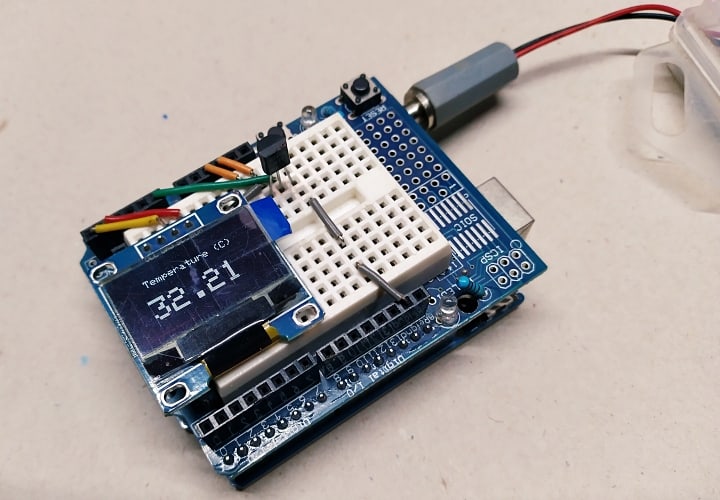
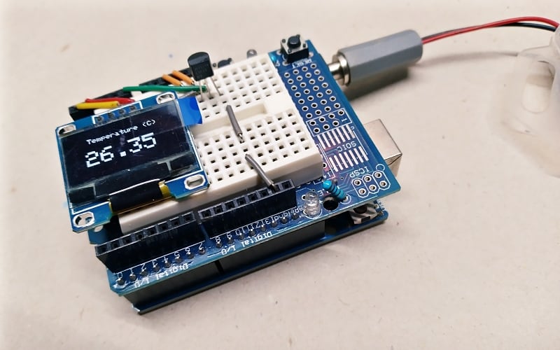
All that is left is to copy-paste the above code and upload it to your Arduino board. Once all that’s done, you’re ready to go with your quick digital thermometer prototype. If everything is done correctly, your prototype thermometer will now begin to show the ambient temperature level (take a look at the picture below).
When you power up, you’ll see the Adafruit logo on your display screen for a while, which’s quite natural (if the splash screen doesn’t bother you, simply forget about that). But luckily, you can change the default logo that appears as a splash screen on the display panel while using the Adafruit_SSD1306 library!
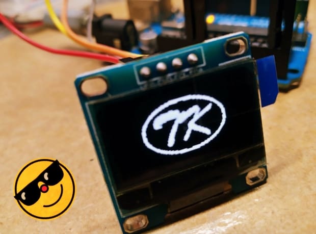
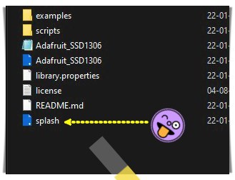
If you want to change the splash screen from the default Adafruit logo to yours you’ve to change the “splash.h” file which can be found in your Arduino library directory in the Adafruit_SSD1306 folder. I’m not going to explain the splash screen hack right now, it’s too long, but I’ll include the key steps you need to know in a future post.
And then, in the end, you’ve the project details of a quick and dirty digital thermometer with a pretty nice display screen. Give this little project a try for yourself. It’s my pleasure to hear your suggestions. See you next week!