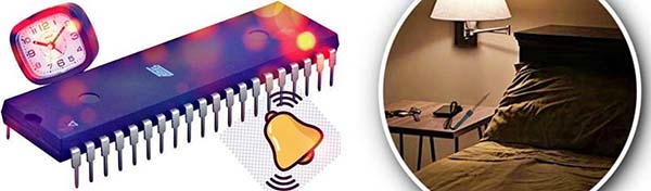
We’ve controlled electrical appliances through a number of wired and wireless control methods. That’s okay but how about controlling them with the alarm signal of a cheapo quartz table clock?
This article demonstrates the simple circuit of a table clock adapter with a single off-the-shelf IC to allow a common table clock to control an electrical/electronic appliance – a “Good Morning Lamp” for instance.

Obviously, the core electronics would need to be expanded to build your own fabulous hobby electronics projects. However, this little design idea itself is perfectly suitable for a one-evening construction project.
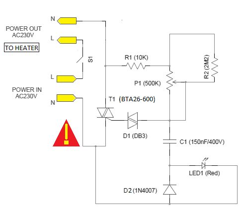
Ready to get into the table clock adapter project? Great! Below you can see its entire schematic.
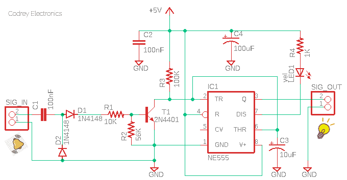
This little adapter circuitry can be used to build either event-initiated or programmed electronic switches to control a lamp (or something similar) when it is desired. Note that this adapter is able to control an electronic switch, that further controls the required load, not only with a quartz alarm clock signal but also with many other audio/tone signals.
This section discusses a few things to look for when dealing with the given design concept as this project theme may seem a bit strange to some readers. Nevertheless, I won’t like to delve into an in-depth design description because the 555 timer chip-based event detection idea is pretty simple and it’s already employed in a number of hobby projects published earlier in this space. The input trigger signal (quartz clock alarm signal) actually requires an explanation, so, let’s look into that!
The principle components in a quartz alarm clock are the power source or the cell, the quartz crystal resonator, the integrated circuit, the stepping motor, the gear train, and ultimately, the hands and the dial. For the alarm sounder, usually a magnetic buzzer (not a piezo buzzer) is used.
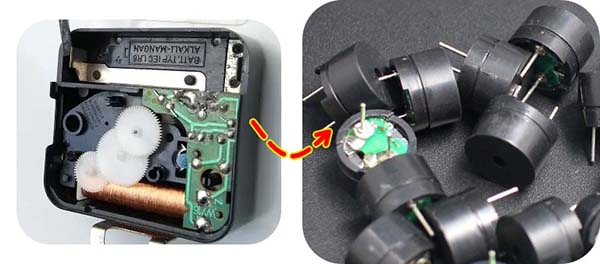
A magnetic buzzer, also known as electromechanical buzzer or electromagnetic buzzer, is similar to a piezo buzzer in that it is used to produce a tone. However, magnetic buzzers differ from piezo buzzers in their core functionality. This is a sample datasheet https://docs.rs-online.com/4e86/0900766b815934a8.pdf
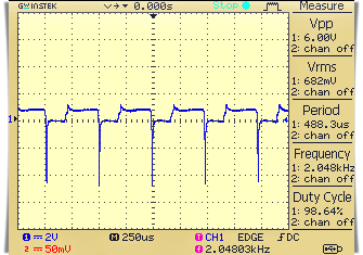
In a common quartz alarm clock, the magnetic buzzer is usually driven by a high-frequency tone signal, and the peak-to-peak voltage (Vpp) appears across its terminals will be a two-fold of the actual dc voltage used to operate the quartz clock’s electronics (see a random scope trace below).
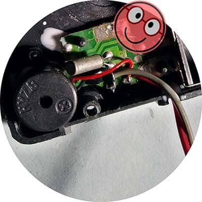
The quartz clock engine (also known as quartz clock movement) will need a simple modification to allow it to be used with this adapter. First off remove the battery, prise the engine case apart, and then carefully solder two wires to the buzzer pins. Finally, clip back the case together. Now you’re ready to go!
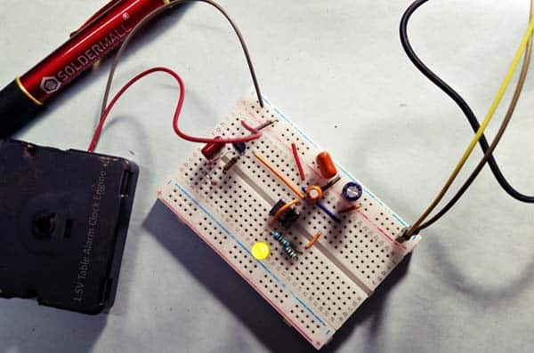
Construction of the adapter circuitry is a simple task. After construction, connect the input terminals (SIG_IN) of the adapter in parallel to the internal buzzer terminals of a quartz alarm table clock through the two wires you already extended from the clock engine.
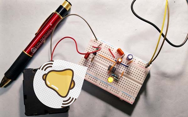
From now on, when the clock alarm is activated at a time set by you, the adapter delivers a logic-high (H) level output through the output connector (SIG_OUT). The yellow LED is a standby indicator that turns off when the adapter is activated with the clock alarm signal input.
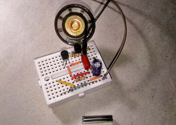
This is a quick snap of my breadboard version I prepared for a sanity check.
In order to make it compatible with microcontroller circuits, the adapter is designed to run on 5VDC power supply. So, the logic-high level output voltage (in unloaded state) will be around 4.4v. You can certainly use this output to drive a relay or thyristor through an appropriate driver circuitry, rather than linking it to the I/O of a microcontroller. However, a microcontroller, loaded with a great code, helps you build amazing projects. Mind it.
In conclusion I’d like to say, this post provides a quick demonstration of a simple solution for making a quartz alarm clock adapter for electronics projects and can be the basis for other more specialized projects. This writeup only covers a mere application example, which leaves the concept open to great enhancements left only to your imagination.
I hope this note inspires you to tackle your own projects – whatever your skill level. Let me know how you get on!
List of Components:
- IC1: NE555 (https://www.st.com/resource/en/datasheet/cd00000479.pdf)
- T1: 2N4401 (https://www.onsemi.com/pdf/datasheet/2n4401-d.pdf)
- D1-D2: 1N4148 (https://www.vishay.com/docs/81857/1n4148.pdf)
- LED1: Yellow/5mm
- C1-C2: 100nF
- C3: 10uF/16v
- C4: 100uF/16v
- R1: 10K ¼ w
- R2: 56K ¼ w
- R3: 100K ¼ w
- R4: 1K ¼ w