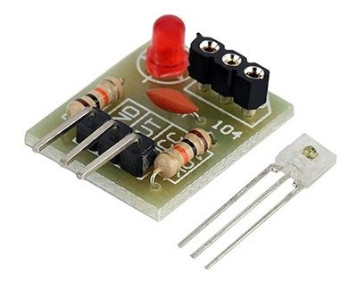
This article introduces a laser receiver sensor module available on the web. The module, named “Laser Receiver Module Non-modulator Tube Laser Sensor Module”, comes as a cheap module usually without a user guide. So it is handy to know what it can do, how it works and learning how to interface it to your own projects.
Potentially confusable legend!
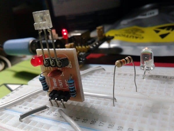
Most first time buyers will get a shock upon the receipt of the packet as the sensor element is included in the packet as a loosy component, and sadly there’s no instruction on how to insert it into the sensor socket of the module. If you follow the legend on the PCB, you will be in trouble because the PCB is actually designed for a temperature sensor module, and hence the legend merely refers to the DS18B20 temperature sensor! So remember to insert the 3-pin sensor into the socket as shown below.
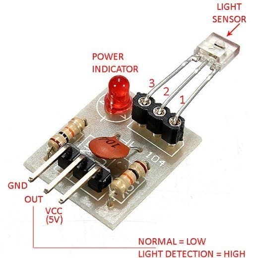
A cryptic 3-pin sensor?
The 3-pin sensor is actually a minuscule light sensor (receiver) diode with an integrated amplifier and an open-collector transistor at its output. Output of the module, designed to operate on 5VDC power supply, can only go low (L), and the open-collector transistor inside the 3-pin sensor can sink about 20mA current. The description poor Chinese description “non-modulator tube” actually points the fact that the light sensor can handle any source of light and it’s not like a 3-pin infrared sensor module (TSOP1838 for example) that only detects an infrared pulse train within a particular frequency band.
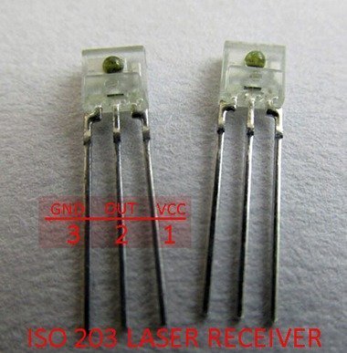
You may ask how did I obtain the above information. Frankly, I spent hours and hours on web to unwrap the mystery but finally got decent info from an online Chinese reseller. Now to the cool part – the sensor is known in China as “ISO203 Laser Receiver”. You can see its pin notation in the image provided below.
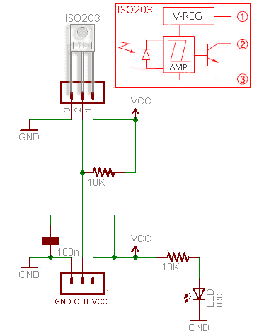
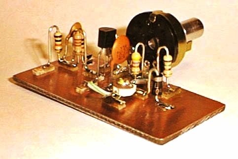
Module circuit diagram
Following is the retraced circuit diagram of the “Laser Receiver Module Non-modulator Tube Laser Sensor Module”.
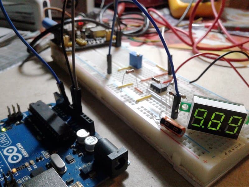
Module quick test setup
In order to test the module you can use the 5V circuit diagram given below. As you can see the setup consists only one amber LED and its current limiter 10K resistor connected across the output of the module (OUT & VCC).

The amber LED remains in lit state, however, in case of the reception of a strong (visible or infrared) light beam, the LED goes off to mark a high-level (H) shift at the output of the ISO203 laser receiver sensor. A simple test mechanism, that’s all!
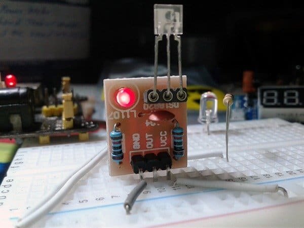
Next is the random snaps of my quick test setup wired on a breadboard:
Improved output adapter circuit
Even though you can replace the LED in the previous circuit with a suitable opto-coupler to make an isolated output interface (you can obviously use the module’s logic-level output directly too), circuit diagram of an improved output adapter is also provided here. The circuit wired around the Profoundly honored timer chip can be used as a medium-current, inverting or non-inverting line driver that can sink or source load currents up to 200mA safely.
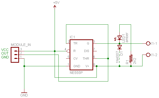
The given ‘inverted’ configuration, however, gives a low-level (sink) output when the module’s output becomes high, and vice-versa. Nevertheless, it’s easy to substitute the LED (LED1) with an appropriate solid-state relay (SSR) or electromagnetic relay (EMR) to drive an external interface or electric load. It’s possible to wire such relays across the output and ground rails of IC1, as well.
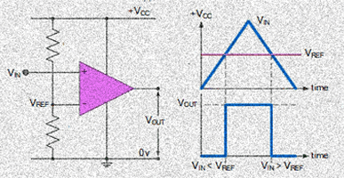
To work this out, you need to understand the role of the timer chip in the presented circuit. We commonly think of the 555 as a timer/oscillator chip, but it’s actually very well suited for simple sink/source driver applications alike the one shown here. When the ‘sensing’ pins (2 & 6) of the chip are taken to a voltage above 2/3 of the supply voltage, the output pin switches low (sink-mode). Then they are taken below 1/3 of the supply voltage, the output pin swings high (source-mode). Further, the sensing pins are voltage sensing and demand rather less input drive current.
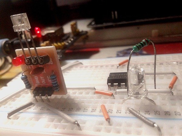
Now, another snap from my workbench. This time it’s one candid photograph of my improved output adapter setup wired on the breadboard.
Better beam of light
As pointed (and observed) previously, the laser receiver sensor reacts positively not only to laser/infrared light but also to visible light. And for this reason, if you’re planning an exclusive laser-beam based project, you will need to encircle the active face of the sensor with an opaque tube to prevent ambient light from interfering with the sensor.
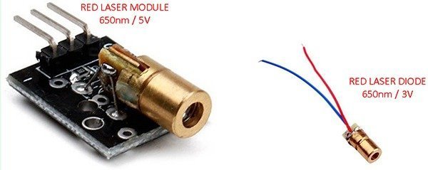
For the common light-beam source (i.e. the light transmitter), try the “Red Laser Module” or the “Red Laser Diode” available everywhere online for cheap. Both the laser module and the laser diode transmits an intense (5mW) narrow laser beam (650nm wavelength) – a red dot extends up to 10 meters. Since the “5V” laser module comes with all necessary parts soldered onboard, you can use it quickly in your project. But for the laser diode, you must add a suitable current limiter resistor to run it on 5VDC. I tested the red laser diode with a 82Ω series resistor (@5VDC).
Let’s discuss more
Next in the laser-beam series is an advanced “laser fence” project currently under development. The diy project that uses a modulated laser beam is likely to be available to you all before long. Stay tuned until it sets alight by laser!
Further reading
Hi Any help with that reseller please? i need lots of these for a project and dont fancy having to waste a load of pcbs buying the ready made boards just because they are too bulky would much rather buy the sensor and do the rest myself 😀
@dave; Check out this link https://www.aliexpress.com/item/32813644324.html Thanks!
Thanks a lot for the info, that ISO203 name is something I have been looking for.
Miguel Lam: Thanks for checking it out, I appreciate the feedback.
BTW, I’ll come up with another funny project based on the same sensor soon. so please watch out this space occasionally. Have fun with your projects!
Mr. Hareendran,
First of all, thank you for the information and the time you took to get it to us. Secondly, I don’t know much about electronics (just enough to get me into trouble sometimes), but I’m really interested in the uses of these devices. I’ve been tinkering with Arduinos and ESP microcontrollers and would like to use lasers and laser receivers in a project of mine. Do you know of or can you point me in the right direction on finding the proper code to use these items?
Thank you again,
Ron.
Ron K: Welcome! Happy to see your inspiring comment.
Yes, the little laser diodes and receivers are pretty good things for do it yourself projects. We can build many funny projects using them with or without microcontrollers.
I will try to publish more laser projects here later. Stay tuned.
In the meantime, you may go through my earlier projects similar to these:
https://www.codrey.com/electronic-circuits/laser-diodes-drivers-an-improved-primer/
https://www.electroschematics.com/laser/ Good luck 💫
Great work! But the product seems to be named as IS0203 not ISO203. Correct me if I am wrong
Abhishek: Surprisingly, we can see this in both names, but I’m not sure what the exact part number is!
See:
“LASER RECEIVER ISO203” https://www.katranji.com/Item/337627
” IS0203 Laser / infrared receiver Sensor” https://uge-one.com/is0203-laser-infrared-receiver-sensor.html
Thanks!
Amazing in depth review! I am trying to build an array of laser emitters and receivers to detect falling objects inside a shaft or tube. In your closing remarks you mentioned an advanced “laser fence” project, but I could not find it in your blog posts. Can you confirm if this is still in your plans? Looking forward to it! Greetings from Germany!
Rob: I apologize for the long delay in preparing the sequel. Thank you so much for your gentle reminder 👍
Actually it’s almost finished, but still needs a few more parts to complete . As you’re aware, the coronavirus spread around the globe, so did the components shortages. The entire supply chains were clogged by the pandemic, and most sellers in China couldn’t ship electronic parts to my country – India.
Hopefully, you can see the promised post within 4-6 weeks. BTW, I may redesign the laser fence concept using some common components lying around my workbench to expedite the submission. Keep the suggestions coming!
Regards
TK
Thank you kind sir. You’ve saved me untold hours of frustration. I’m so happy I could cry.
Christian Brower: Thank you so much for your kind words, I really appreciate you taking the time out to share your experience with me. All good wishes!
which part of the sensor (the clear rectangle with the dot) do we want the light/laser to shine on for best results. Do we want the laser to hit the side of the sensor that has the “dot” on it, or on the smaller “top” surface? Your diagram is very good, but I can’t tell what part the red arrow you put on the diagram is pointing at
todd; As observed, the “dot” side is its most sensitive face.
See also https://www.katranji.com/tocimages/files/337627-111110.pdf
Thank You!
Any update on the advanced “laser fence” project
@Xenophon: Thanks for the inquiry. It’s done, and now I’m preparing to submit it. The project will probably be available here by the end of next month.
BTW, as I pointed out in a previous comment, due to the limited availability of some key parts I was forced to change the initial concept a bit (Simply, I just used what I had to mockup it)!
Could you post a link to this article? Couldn’t find it on your profile.
Any update on the laser fence project? I couldn’t find it in your list of articles.
Xad Ulili: Almost done and ready to submit. I need to take a few more photographs to complete this, but there may be delays as I am renovating my lab. I am deeply sorry for the lapse on my part. Thanks for the reminder!
Thanks a lot for this post! You really did a great job as it’s effectively far from being obvious to find information on these components! 😀
@Olivier: Thank you for your comments. Really appreciated!
Posts like this take weeks and lots of hours to prepare for. Sometimes I wonder why I do them, but comments like this that keep me going. Cheers!
Wow, great post; I’m looking to use this for my own project. Would you happen to know if this would work to detect a 905nm laser?
Anthony Ortiz: Not sure, but according to the datasheet ISO203 laser receiver’s typical peak wavelength is 900nm (https://europe1.discourse-cdn.com/arduino/original/4X/7/9/3/793ab0c30795d72f4ee16d84dbf98311b80342ac.jpeg).
Thank you for your comment. Really appreciated!