Resistor, this is a common electronic component seen in electronic circuits. This is one of the basic components used in Emergency lighting, Medical Devices, Battery operated equipment, and many more applications.
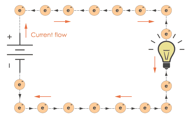
The word Resistor came from the property of resistance, which means to oppose current. Resistors are nothing but hurdles and obstructions in the path of electrons moving in a wire. After current flows, there is a fall in voltage (potential difference) which makes the flow of current possible.
Surprisingly enough, the resistor is inactive (passive) in nature and technically called as a passive component due to the difference between active and passive elements. In short, Active elements are the devices which need an external trigger source to operate reliably. Similarly, Passive elements are the devices which don’t require external power sources to operate and solely they are independent.
To have a clear idea, here are examples of active and passive elements. Components like Diode, Transistor, Vacuum tubes comes under active components. Furthermore, components like resistor, capacitor, and inductor are known as passive components.
Let me be a bit more specific. Active components like the diode need threshold voltage to operate, say 0.3V (germanium) and 0.7V (silicon). But, resistor doesn’t need any specific voltage to function properly. It starts working as soon as you apply to the supply voltage.
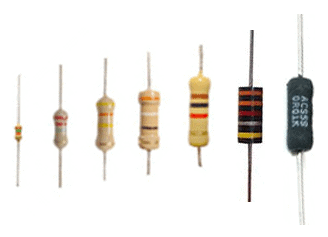
In simple words, I can say all passive elements (resistors) have energy storing capacity and hence called energy storing elements. When you open any electronic device you may find tiny colored cylinders with different shapes and sizes.
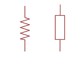
 Typically resistor can be represented by following schematic symbols:
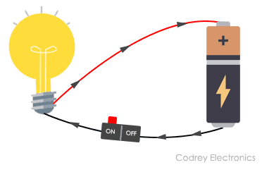
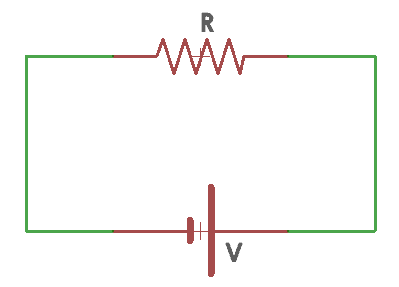
Besides, the resistor is having some interesting property called “resistance“. And, believe it or not, every circuit is made up of wire and is having the internal resistance particularly the battery shown below. It is indicated by the Greek symbol Omega (Ω).
For easy understanding of resistor, let’s take the analogy of hydrodynamic model. In hydrodynamic model-based approach resistor is considered as a pipe. Whenever a fluid flows through a pipe, the walls get pressurized and thus reducing the potential energy of the fluid. The size of the resistor varies based on the piping diameter.
Smaller resistors are equivalent to larger pipe allowing higher flow rate through the pipe.
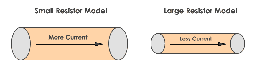
Likewise, larger resistors are analogous of smaller pipe having constrained fluid flow. Technically saying, resistors blocks the flow of electricity and you can control current in a circuit. This is often referred to as resistance.
But to hold in the current you need to know two parameters i.e. voltage and resistance. This relation is evaluated using Ohm’s law. Ohm’s law definition says current flowing between two electrical points is directly proportional to the voltage at the component and resistance being constant.
Here is the mathematical equation invented by George Ohm that plays a key role in resistor working. The Working principle of resistor depends upon three quantities voltage, resistance, and current.
Based on these, we can redefine ohms law in two forms.
Scenario 1: Voltage is constant
I=V/R
Where,
‘I’ indicates current flowing through the conductor represented in Amperes.
‘V’ is the potential difference (measured in volts) across the electrical points.
‘R’ is the resistance (measured in ohms) of the component inversely proportional to current and voltage.
When resistance value is high, current in the circuit decreases and vice versa.
Note: The Resistance and current are inversely proportional when the voltage is made constant.
Scenario 2: Current is constant
R=V/I
When resistance increases voltage increases, and if resistance decreases voltage decreases. Here resistance and voltage are directly proportional to each other.
Note: The Resistance and voltage are directly proportional when current is made constant.
Now, here is a question who is new to analog electronics. Does a resistor have a polarity and how to connect? The answer is No. But that’s only half the story. The reason is, they are passive in nature. Hence limits the current without taking into consideration the direction in which it is connected.
Power Rating
The current limitation in resistor depends upon the types of resistor. Mostly carbon composition resistor and metal film resistors are used. Other types of include variable resistors also called potentiometer, wire wound, and carbon film resistors. If the current flow is more through a resistor, then its power rating will be high.
The resistor power rating indicates the capability to withstand high current flow through its body. Here is an example. I want to connect a device which draws a max current of 100mA. Now, if I place a resistance that cannot withstand current it will burn up and there may be a chance of damaging the circuit.
To overcome this problem you should pick up high wattage resistors (1/8 and ¼ watt). As power rating increases the size of the resistor also increases. As you know resistor gives voltage drop, the manufacturing is done in a controlled manner to produce the desired resistance. The range of resistance value varies from less than 1 ohm and greater than 22 mega ohms and it cannot be negative.
To maintain better power handling capability standard nominal resistance values have to be preferred. Meanwhile, the size of the resistor decreases with an increase in power wattage rating.
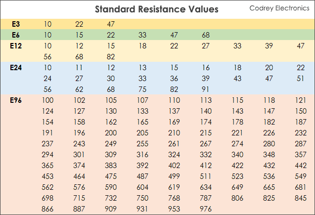
Standard Resistance Values
In fact, the standard nominal resistance is the average or typical rated resistance specified and designed by the designer or manufacturer. Here are the standard resistor values used in the industry.
Indeed, the resistor has some tolerance value (error in resistance value) stated as “how much more or less the resistance of a resistor has, other than its actual resistance”. The most commonly available tolerances are 1%, 2%, 5%, 10%, and 20%. In essence, resistors can be connected in multiple ways. They can be joined in Series connection, Parallel connection or combination of series and parallel.
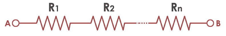
Resistors in series (daisy chain connection) form have some voltage drop across them and the current is same in all resistors.
For example, if two resistors R1 (1K ohm) and R2 (2K ohm) are connected in series and if some current say 4mA current flows through them the voltage drop across R1 is 4V and R2 is 8V.
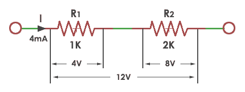
From the ohms law V=IR, The total voltage across the two resistors in the series network is 12V. The total resistance is given by the sum of the individual resistances.
R=R1+R2=1KΩ+2KΩ=3KΩ
Moreover, resistors connected in parallel have the same potential voltage across them and current is different for each resistor. Here the current will divide through each resistor.
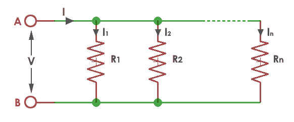
Hence total current (I) = I1+I2. To calculate current in parallel circuit, assume an input voltage (V) of 12V is applied across the resistances R1=1K and R2=3K.
Applying the current equation of ohms law, I1=V/R1, and I2=V/R2
The total current is given by I=12/1000+12/3000 =12mA+4mA=16mA
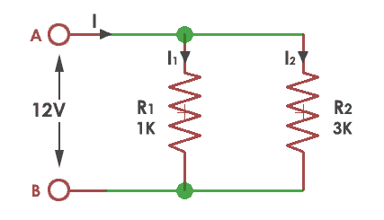
Resistor in Parallel – ExampleAnd the total resistance in the parallel circuit is the sum of the reciprocal of individual resistances.
R= 1/R1 + 1/R2 = 1/1000 +1/3000 = 750Ω
Therefore, the overall resistance in the parallel circuit is 750 Ω. Now, you may be probably wondering: how to measure resistance in a circuit without a formula?
You see there are multiple ways to calculate, check this out:
- Using ohmmeter
- Multimeter
- LCR meter and
- Color coding technique
Finally, the important thing to know is: why to use resistor in a circuit? Here are some of the applications of resistor that are used in the industry to make efficient hardware blocks.
Resistor Applications
- Some components (such as LED’s) consumes more current and burns out sometimes. To avoid this, resistors are used for limiting the current.
- Minimize voltage by using a voltage divider network
- To short two points in a printed circuit board (Zero ohm resistor) without using a jumper.
- To reduce noise (Metal foil resistors)
- In heater elements like oven and electric heater (Power resistor)
- Volume control applications like Stereo (Potentiometer).
- To produce different voltages to power on embedded modules like Bluetooth, Wi-Fi, and ZigBee.
- To protect the sensitive components or IC’s from accidental blow ups.
Summary
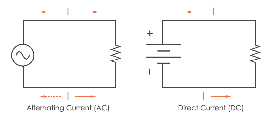
To top it off, resistors resist direct or alternating current. It is an imperfect conductor and a basic electronic component that is used in analog circuits. By controlling the electrons going through a resistor, you can make a circuit perform different things.
Resistors may be the primary building block of electronic circuits, so you may see them many electronic projects. By now, you probably have some unanswered questions about how to measure resistance and they will be cleared in later part of the coming tutorials.