Validating the calibration of an electronic test and measurement instrument such as a digital voltmeter (DVM) is very crucial especially after many years of service. Nowadays, it is easy to build a compact voltage reference with the help of precision voltage reference ICs, and for high-impedance DVMs, the AD584 (http://www.analog.com/AD584) precision programmable voltage reference IC (from Analog Devices) is a welcome relief. Before we go deep into the actual try out, let’s take a good look on the most important specifications from the official datasheet (Rev. C) of AD584JH – the “8-Pin Metal Header (TO-99, H-08)” – pin programmable, precision voltage reference.
AD584 Practical Application
The AD584 IC is a venerable 8-terminal precision voltage reference offering pin programmable selection of four popular output voltages: 10.000 V, 7.500 V, 5.000 V and 2.500 V. Other output voltages, above, below, or between the four standard outputs, are available by the addition of external resistors. Besides, the output of the AD584 is configured to sink or source currents. This means that small reverse currents can be tolerated in circuits using the AD584 without damage to the reference and without disturbing the output voltage. The input voltage can vary in the 4.5 V to 30 V range. Since the quiescent current demand of the AD584 is low enough (~ 1 mA), the setup can be easily powered by a small 12V dc source, or from a 10F20 type 15V alkaline battery pack if required.
In terms of the versions, I’ve seen “J”, “K”, and “L” in the list, clearly “L” was discontinued back in 2012 (as I’m aware of), and “H” suffix indicates the TO99 metal package. The basic specifications are quite impressive, though naturally, it depends on the exact version you have.
With power applied to Pin 8 and Pin 4 and all other pins open, the AD584JH produces a buffered nominal 10.0 V output between Pin 1 and Pin 4. The stabilized output voltage can be reduced to 7.5 V, 5.0 V, or 2.5 V by linking the programming pins as shown in the next table.
| Output Voltage (V) | Pin Combination (Programming) |
|---|---|
| 7.5 | Pin 3 + Pin 2 |
| 5.0 | Pin 2 + Pin 1 |
| 2.5 | Pin 3 + Pin 1 |
AD584JH DVM Checker
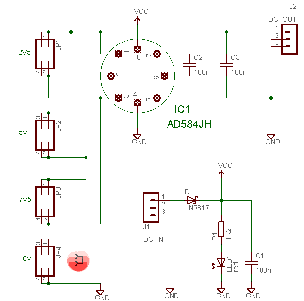
Let’s see how to build a simple circuit of a DVM voltage reference. Fortunately, the implementation of the AD584JH is straightforward, and construction on a little piece of veroboard should not present any undue difficulties (bear in mind the J-grade variant is specified only to 0.3%). The input and output voltages are on 0.1″ male-headers, and the voltage selection is made by moving a link along a row of standard (2x) jumper-headers (the idea behind the usage of 2x jumper-headers is to minimise errors caused by contact resistance). Take care there is no output protection beyond a small (100n-330n) decoupling capacitor, input is protected against reverse polarity by an 1N5817 Schottky diode though.
The AD548JH contains a precision bandgap voltage reference, an op-amp, and a laser-trimmed resistor network around the op-amp. By default, the resistor network provides the required gain to step up the 1.215V from the reference to 10V. Although by shorting together pins, 2.5V, 5V or 7.5V can be obtained, you can try external resistors to achieve other voltages. The given design is good for DVMs with high input impedance (>100K). For testing lower impedance equipments, the output of this circuit may be followed by a simple unity-gain opamp (buffer) circuit (anyway not tested by me yet).
The AD584JH also has a strobe input (pin 5) that can be used to zero the output. When the IC is used as a power supply reference, the supply can be switched off with a low-level input at pin 5 (with less than 200 mV the output voltage go to zero). This feature is not required/utilized here.
Lab Test Report
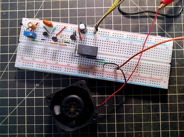
Well, let’s see how it performs. For the evaluation, power was given from my lab power supply set to 15.0V, and I used one (borrowed) Fluke 8920A True RMS Voltmeter for the measurement. My lab was at 28°C.
| Output Mode | Measured Voltage |
|---|---|
| JP1 - 2.5V | 2.50102 |
| JP2 - 5.0V | 5.00158 |
| JP3 - 7.5V | 7.49897 |
| JP4 - 10V | 10.00254 |
What’s Next?
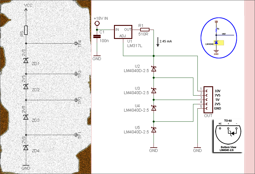
Alternatively, you can DIY something different as there are plenty of designs out there. In principle, a precision voltage source is useful to quickly check that a voltmeter is basically doing the right thing. For many years now, whenever I’ve needed a quick bandgap voltage reference, I’ve turned to the renowned LM4040D (2.5V version) in TO-92 package. We can build a 10V reference by putting such four 2.5V references in series, ofcourse, with the same setup we also have 2.5V, 5V and 7.5V outputs. A simple resistor (or a precise current source – for better results) is all we need to supply operating current to the references. I hope this brief idea is of interest. Feel free to carry on at your leisure!