Any electronics experimenter can connect an analog sensor to a microcontroller and run it with the help of a piece of code. Sometimes there’s a reason to provide a clean digital signal input to the microcontroller, but providing a clean digital signal (in lieu of the natural analog signal rendered by the sensor) for further processing by the microcontroller is harder than it looks. Making a hardware interface aright for such an application is harder still!
A Spark of Idea
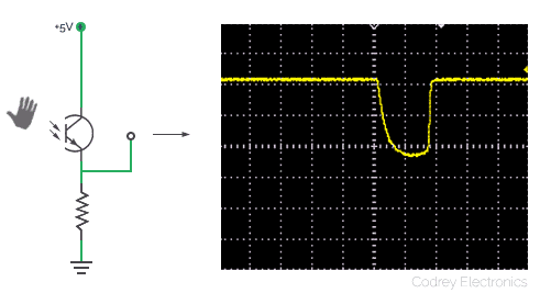
Now listen, recently I wanted to build a microcontroller-based moving shadow sensor so I wired a ‘light-sensitive’ potential divider (at the front-end) with a PT333-3C phototransistor and a 10KΩ resistor. It’s okay but I simply got a clumsy output signal when I waved my hand over the phototransistor (hoped for a clean square pulse – ha ha), and the result (see figure below) forced me to think about an add-on hardware-interface that can make my signals ‘in shape’.
I know that but really dislike the way of complementing the code (for the said project in hand) by merging a few more lines to handle extra tasks, like for instance, signal averaging and peak detection. Fortunately, I became aware of a ‘hardware’ idea documented by Microchip (www.microchip.com) – the ‘data slicer’ based on a single op-amp.
The Data Slicer
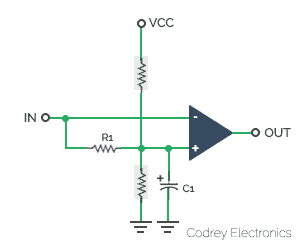
A data slicer works by equating the incoming signal with a sliding reference derived from the average dc value of the incoming signal. The dc average value is obtained using a simple low-pass filter. Following is the basic schematic of an op-amp data slicer. In the schematic, the optional resistors (only one at a time) provide a slight bias to the reference (either high or low) to give a preference to the output state when no data is being received.
My Data Slicer/Shadow Sensor Module
How is the above idea possible in real-world to implement this with using a cheap op-amp? At minimum what needed is a single op-amp from the dual-comparator chip LM358. Since my necessity is a moving shadow sensor this will be cheaper and more workable. LM358 is obviously a poor choice when speedy transition is important, as once the output saturates (literally) at the supply rails, it requires a significant amount of time to recover. Anyway, not an issue here because the shadow sensor is not a too fast one. Okay, now I’ve a circuit idea with one op-amp functions as a comparator, and delivers a clean pulse at its output ready to interface with a microcontroller. Tried and tested schematic of my ‘microcontroller-compatible data slicer/moving shadow sensor module’ is shown below.
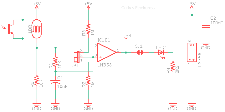
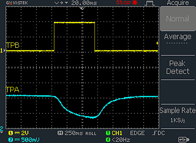
In the given configuration, output (TPB) of IC1 gives rising pulse (~3.6V) when it sees a dip at its input (TPA). See the oscillogram below. Centre frequency of the low-pass filter (R1-C1) is around 1.6Hz. Default (and preferred) position of the 2-way jumper header (JP1) is ‘normal’ (1) but ‘invert’ position (2) can be selected for a low-level (falling) output. LED1 works as the output status indicator but for debugging, which can be disabled through the solder jumper (SJ1). This 5V TTL compatible circuit should be run from a regulated and ‘clean’ 5V dc supply.
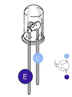
If in demand, try to substitute the 5mm LDR with a common phototransistor like PT333-3C (www.everlight.com). The PT333-3C (not PT333-3B) is a cheap 5mm LED type ‘water clear’ n-p-n phototransistor sensitive to both visible and near-infrared radiation (see next figure).
Finally
Note that the performance of the circuit depends on the type of the light sensor and how the shadow level changes, left as an observational exercise for the reader. Needless to say, it’s possible to remove the input components to use the circuit as a ‘pure’ data slicer for other application. If so, ensure that centre frequency of the low-pass filter should be high enough to snub the shifts in the dc level while low enough to hand the data being transferred. By the way, note that the shadow sensor may not work as described, if the LDR/phototransistor is exposed to strong lights.
Nonetheless, there’s a lot to experiment with. What I’ve presented here is just the results of a few hours of tinkering. There’s certainly enhancements that can be made, both in concept and in hardware. So just make yourself a simple data slicer and start slicing!