This little post is a quick rescript of RMS and TRMS. As you know, this is not a popular or frequently discussed topic. So, let us jump in!
RMS and TRMS
RMS stands for Root Mean Square and TRMS (True RMS) for True Root Mean Square.
RMS is the mathematical formula internally computed by the RMS-capable instruments to take measurements. This formula is simplified by the instrument to consider only the positive peak value of the sine wave (VRMS = VPK /√2).
However, since this method considers the peak value of the waveform, the RMS measurement is reliable only when the waveform is a perfect sine wave.
Sine wave is never perfect in real world!
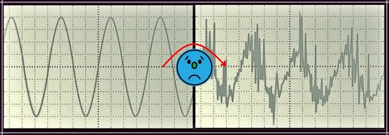
So, TRMS uses more complex mathematical formulas that allow getting a value closer to realism than the RMS. In addition to peak values, it takes several samples of values along each cycle.
Nowadays most of the electrical loads are non-linear loads, and the voltage/current waveform is not perfectly sinusoidal. Therefore, TRMS measurement is preferent for distorted and non-distorted waveform measurement.
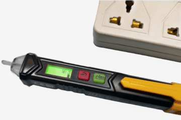
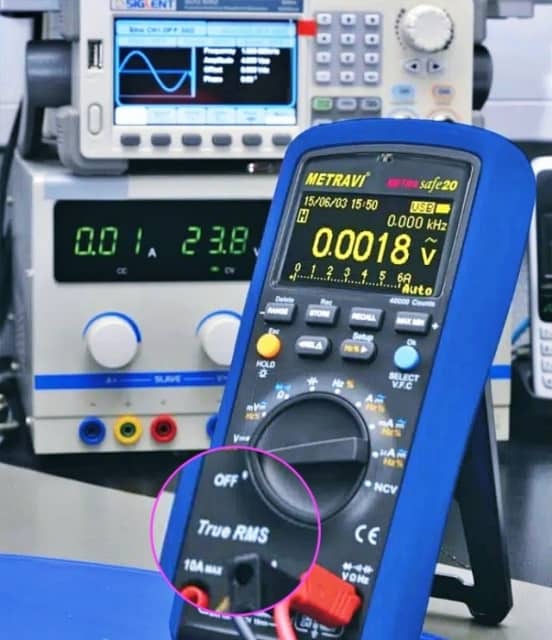
TRMS Meter
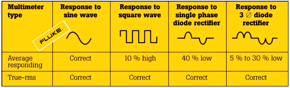
As mentioned previously, the accuracy of the measurement depends on the perfection of the sinusoidal waveform. If the distorted waveform is measured with an ordinary RMS meter it will give an awful error. The ordinary RMS (average responding) meter can measure the voltage and current, and gives accurate readings for linear loads (heaters, incandescent lamps, etc). But TRMS meter can correctly read a non-sinusoidal waveform because its internal circuit calculates the heating value of the current/voltage and gives accurate measurement irrespective of the current wave shape. So, non-linear loads must need a TRMS meter for measuring current and voltage in the right manner.
On the other hand, an averaging meter attempting to measure distorted waves can be up to 40% low or 10% high in its calculations (see below).
In essence, many less expensive digital multimeters are designed to give correct RMS readings when measuring sinewaves, but not when handling non-sinusoidal waveforms (spikes, pulse trains, square waves, triangle waves, sawtooth waves, etc). Better, look for a more sophisticated True RMS multimeter (quite pricey though) to get sensible readings no matter what the wave shape is.
See a bit more details on TRMS measurements here https://www.keysight.com/us/en/assets/7018-01113/application-notes/5988-6916.pdf
On a side note, what does “ac frequency response” in the specs of a TRMS multimeter denote?
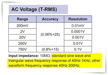
My understanding is that for AC signals with frequency below or above the specified range, we cannot expect to get an accurate AC rms voltage reading!
TRMS Meter – DIY?
Yes, it can be possible to use an Arduino microcontroller to build a little digital voltmeter yourself for measuring True RMS voltage. Here you can see such an RMS Meter Module project https://www.instructables.com/Arduino-RMS-Meter-Module/
Beyond that, this GitHub repository (https://github.com/MartinStokroos/TrueRMS) contains the True RMS C++ library for Arduino which makes it possible to calculate the average value and the rms or effective value of the ADC input signal. This library also calculates the real power, apparent power, and the power factor from both voltage and current input signals.
In Closing
Remember this once more, when you use your multimeter to measure an ac voltage/current, the reading on the meter is a root mean square reading. We sometimes call that value as effective value of an ac voltage/current which has the same effect as a dc voltage/current of the same value.
The important thing to keep note at this point is that a true-rms meter will give you better readings because most cheap meters use an averaging technique for determining the root mean square reading which is accurate only with sinusoidal waveforms (in principle, an average responding meter is calibrated to indicate the root mean square value of a pure sine wave).
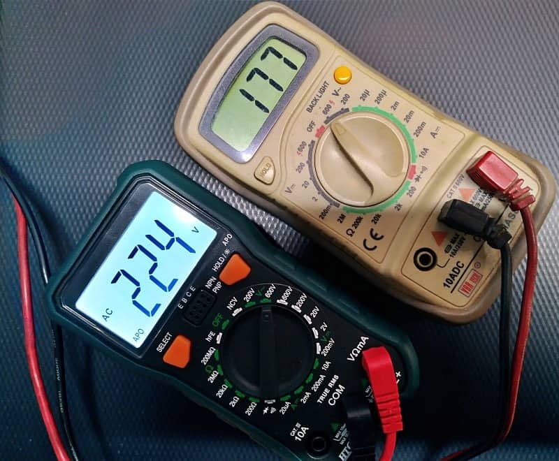
And, as a simple exercise, try reading the output of a modified sinewave inverter using an RMS and TRMS multimeter. You will see that the RMS meter reads low. In the end, I hope that you managed to learn something out of this quick refresher post. Cheers and thanks for reading!