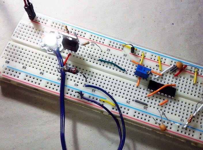
Recently I got an unusual query from a newbie microcontroller hobbyist on how to drive an electromagnetic relay using a bipolar junction transistor (BJT). Admit it, analog electronics is not a piece of butter cake for the most except a few willing scholars!
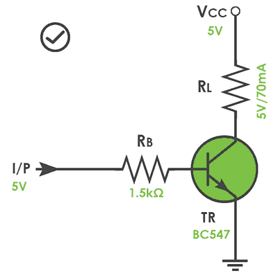
Say you wanted to drive a 5V/70mA rated electromagnetic relay by one I/O port of your microcontroller, and it can cater a maximum current of 20mA at 5V. A sensible choice here is the use of a BC547 NPN transistor as a low-side driver/switch as shown below. The BC547 have a maximum collector current (Ic) rating of 100mA, seems fine for the 70mA relay.
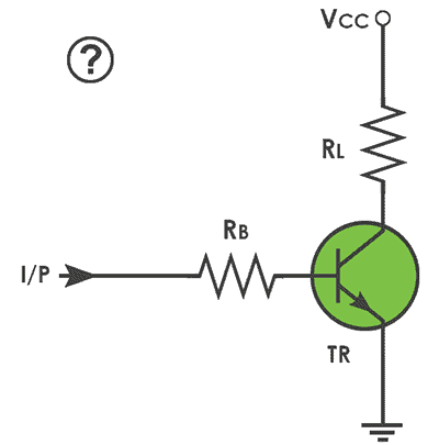
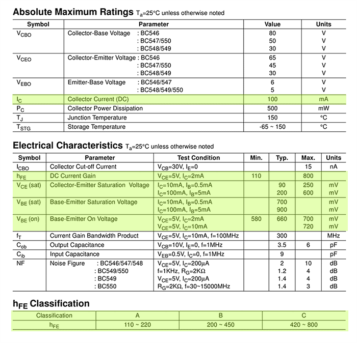
The base resistor (RB) is crucial here to control the amount of current flowing into the base – the base current (Ib), which in turn controls the amount of current flowing through the collector – the collector current (Ic). Since the transistor (TR) is a driver/switch here, suitable value of base resistance (RB) is required for conduction in the saturation region. For this, refer the datasheet of BC547 transistor first and look at the values Vbe, Vce, and hFE. The parameter “hFE” denotes the DC current gain, and this is the vital parameter to consider while driving/switching loads.
In principle, BJT is a current amplifier hence Ic = Ib x hFE. Assume that the 70mA relay may require 100mA to operate, hence Ic=100mA. Since the general-purpose BC547 transistor has a minimum gain just above 100, base current required to saturate the transistor will be IB = Ic/hFE = 100mA/100 = 1mA. Here, formula for base resistance RB = (I/P – Vbe)/Ib. But to ensure that the transistor operates in the saturation region, usually the base current (Ib) is multiplied by a factor of three. Therefore, RB = (I/P – Vbe)/(Ibx3). Note that the base-emitter junction of a BJT behave likes a forward-biased diode with typical 0.65V drop across it.
Now to the real-world maths:
- From the transistor datasheet, find the values Vbe (sat) and hFE : (0.77V and 100)
- Note down the base current (Ib), and the control input voltage (I/P) : (1mA and 5V)
- Calculate the value of base resistor (RB) : RB = (I/P – Vbe)/(Ibx3)
- RB = (5-0.77)/ (1×3) = 1.41K Ω (1.5K Ω is the nearest standard resistor value)
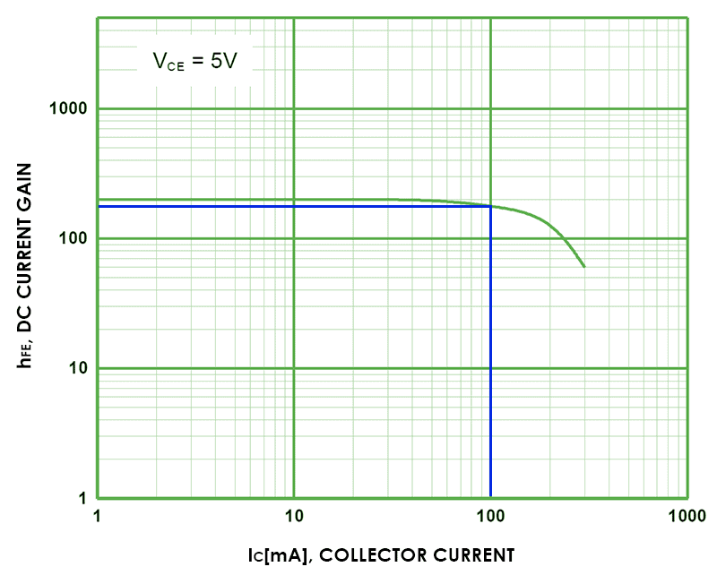
When you refer the datasheet you can find that Fairchild’s BC547 transistor actually has three hFE classification – BC547 has a minimum hFE of 110, BC547B has 200, and BC547C has 420. When choosing the hFE value for driver/switch transistor you should always consider the minimum rating as the worst case because you want the transistor to conduct in the saturation region. The graph below shows hFE on the y-axis and collector current on the x-axis, and the marker (blue) is set to get maximum Ic of 100mA. Also look, if Ic increases, hFE decreases (trickiest to follow indeed).
& some key parameters in the datasheet that you must consider:
Well, now you’ve completed the build of a demand-driven circuit, and it’s worthy for the intended purpose. However, if you want to drive a dc motor in lieu of the electromagnetic relay things get more serious especially if you’re in a hurry to drive the motor with pulse width modulation (PWM) technique. Let me smooth the surface of the wood – stay tuned for a sequel!