I have no idea if you’re the type of maker who browses e-commerce sites looking for cheap, interesting things for your hobby electronics projects or not. However, I most certainly am such a kind of person. I know this may not surprise the regular visitor of this site much. A while back, when I was in a random online search, I came across the listing of an interesting item “Fall Saver Infrared Bedside Monitor” – a compact medial device from Universal Medical Products (UMP).
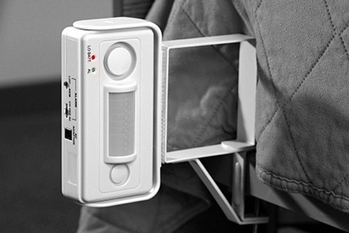
According to the product description publicized by its maker, the Infrared Bedside Monitor alerts a caregiver when a patient attempts to leave the bed. It is designed to be used in nursing homes and medical facilities and is also suitable for home use. The Infrared Bedside Monitor uses infrared technology to discretely monitor any movement from a bed. The device works by emitting a harmless infrared signal which alerts the caretaker, either by triggering an audible alarm or by sending an electronic signal to a nurse’s station at a remote location. Sounds great and seems interesting enough to justify picking up one to mess with! Isn’t it?
However, on a budgetary consideration, I deferred my buy and planned to build a minimalistic version of that smart medical alarm device myself just for a few experimentations. My design is certainly not as nice as the original one on the market – it doesn’t compete with a $$$ priced commercial medical device in terms of features or quality. But in terms of monetary value and overall chasteness, I think my motif is really hard to decline. So, let me share my rough idea of the game with you!

The heart and soul of the schema
A tiny microcontroller is intentionally injected into the core part of this design as it lets you do later elaborations without changing the gist. As might be expected, my pick is the ridiculously cheap and easily available Digispark Attiny85 development board from Digistump. This is the main schematic diagram (v1) of my Fall Saver Infrared Bedside Alarm (FSIRBATK).

My FSIRBATK device is configured to run on an external 9V battery (X1) and an external USB power supply (X2) – however, only one power source at a time. The Digispark microcontroller chip loaded with a little piece of code will do the entire task and its three GPIOs (out of six) handle the rest of the electronics neatly. When powered up, apart from its onboard power LED, the user LED (wired to the P1 port) also lights up but rhythmically as it’s configured as a ‘heartbeat’ indicator.
When the sensor input port (J1) gets an agreeable ‘pull-down’ signal, the system wakes up from its standby state and enables the transducer output port (X3). This active state is indicated clearly by random flashing of the heartbeat indicator. Subsequently, flashers and/or hooters (500mA maximum at 5VDC) attached to the output port (X3) come alive to announce the hazard. This lasts until the sensor state gets reversed.
Note that the port P1 of the Digispark board already has a red LED attached to it, so there is no need to add a new heartbeat indicator (LED1) if you’re using a transparent/translucent enclosure for your FSIRBA. Anyway, there’s no harm in removing the onboard one and adding an external one (it can be removed with a sharp knife).
The dirty microcode
Now to the Digispark Code in the form of the usual Arduino Sketch. I’ve to say that I’m reasonably satisfied with my petty code. But, keep in mind that you’re a better coder than me – so make it more simple and precise and lucid!
int delay_value = 1000;
int fallSense_Pin = 0;
int heartBeat_Pin = 1;
int sounderDrive_Pin = 2;

void setup() {
pinMode(heartBeat_Pin, OUTPUT);
pinMode(sounderDrive_Pin, OUTPUT);
pinMode(fallSense_Pin, INPUT_PULLUP);
digitalWrite(fallSense_Pin, HIGH);
}

void loop() {
digitalWrite(heartBeat_Pin, HIGH);
delay(delay_value);
digitalWrite(heartBeat_Pin, LOW);
delay(delay_value);
int fallsense_state = digitalRead(fallSense_Pin);
if (fallsense_state == LOW) {
digitalWrite(sounderDrive_Pin,HIGH);
delay_value = 250;
} else {
digitalWrite(sounderDrive_Pin,LOW);
delay_value = 1000;
}
}
The lidless infrared rescuer
Since UMP’s product is a successful electronic device, I strictly followed their clever idea and hence picked a passive infrared (PIR) motion sensor as the ‘eye’ of my little electronics, too. Anyway, note that you can use any other sensor setup with the core electronics instead because it can be triggered by an agreeable pull-down signal outputted from any external active/passive sensor or transducer.
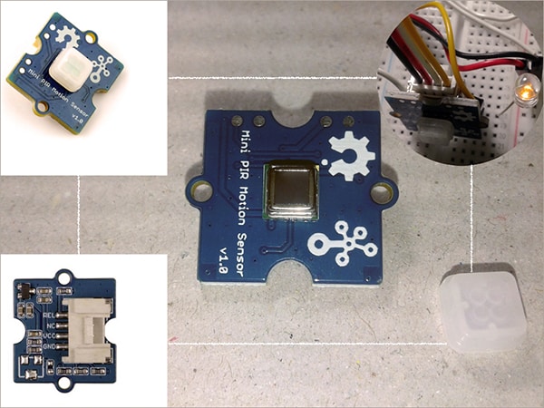
As you might know, the common passive infrared sensor is prone to frequent false triggering and it’s quite natural. Therefore, I choose a digital passive infrared motion sensor module for this application – the Grove mini PIR sensor from SeeedStudio (see above figure). This sensor module allows you to sense motion, usually, human movement in its ambit i.e. when anyone moves in its sensing range (~2m by default), the sensor will output a 1-25s long (~5s by default) logic-high signal (~3V) through its REL pin. The little PIR motion sensor has a detecting angle of 120 degrees, and the working wavelength is 7-14um.
This is the complete schematic of the ‘sensor eye’ for this project. See, one BC547 transistor is used to invert the output ‘logic’. Obviously this surplus transistor can be omitted by changing one line in the code, but the inclusion is intentional – there’s a good reason behind the trick!

The alert generator
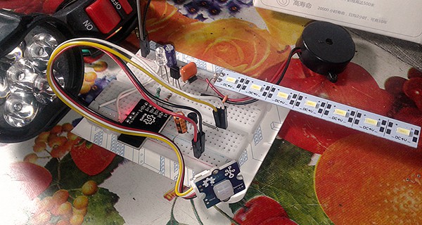
Look, the output driver transistor S8050 (T1) in the first schematic is a low voltage, high current small signal NPN transistor which can manage collector current (IC) up to 700mA. According to the test report included in the UTC datasheet, the collector-emitter saturation voltage VCE(sat) is 500mV (Ic=500mA, IB=50mA). This apparently lets you safely drive certain audio-visual alert generators such as small hooters and signal lamps intended for 5VDC operation. I tested my 5V breadboarded prototype with a small 4V white LED strip and a 5V piezo-sounder (look below).
Finally, dress your electronics!
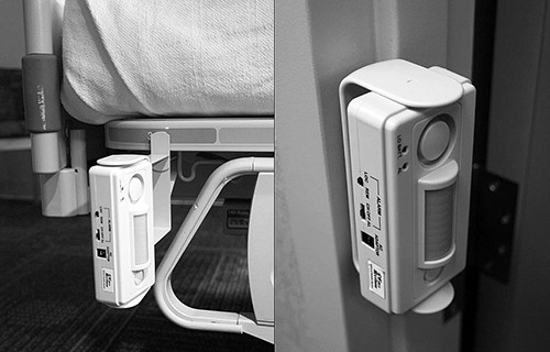
The two circuits are simple enough to be assembled on prototyping boards. A single stripboard has been used by me for the final build (not pictured). All components excluding the motion sensor and the alert generator device are fitted to the board. The entire electronics (including the sensor and alert device) can of course be built into a miniature enclosure making a compact device. A clever casing also provides a good way of attaching the system to the side of a hospital bed frame together with the USB power bank or battery pack. If you don’t have a metal mounting bracket for your enclosure, an alternative method is to attach one Velcro ® strip. During installation, make sure to orient the sensor’s face aright so that it will only be activated when the patient attempts to get up and out of the bed and not activate if a patient twits his or her knees. The figure shown below depicts one of the installation plans proposed by Universal Medical Products, Inc.
Use it to detect a potential fall (not to hinder a fall)!
The poor man’s FSIRBA design presented here can help to reduce the number of bed falls that occur within an institution, but it will not uphold a person falling from his/her bed. It is intended only to alarm a health professional that the person may need assistance. And, this is certainly not a substitute for proper nursing care. The effectiveness of the electronics relies entirely on a contiguous response by the health professional to the alert!
Does this project spark your interest? Good luck in making one, can’t wait to hear from you
Addendum: I’m glad to say that this open-hardware project is still under development. The final real-world snaps together with its printed circuit board and enclosure design files will be posted here after a lengthy field trial.