Today’s composite electronic designs are likely to have many different power supply rails. This is especially true in circuits employing analog electronics along with microcontrollers.
As designs get more complex, the number of power supply rails increase as well. So, getting a simple device to monitor all the voltage rails can be complicated due to the number of different rail voltages.
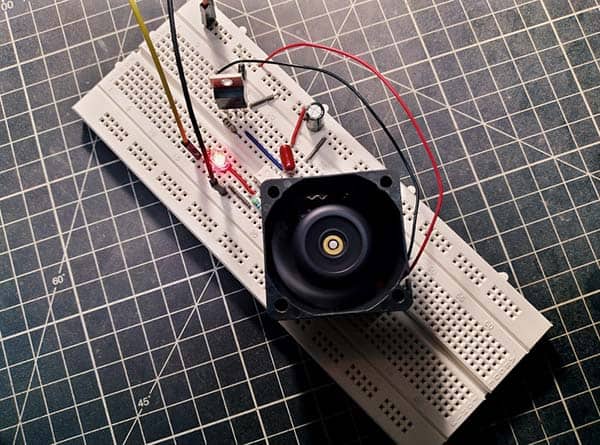
The design idea demonstrated here can be used to monitor a single 3.3V DC power supply rail. The replicable circuitry also has a galvanically-isolated output interface that can be easily handled. What is more, the isolated open-collector output featured in this setup enables multiple output signals to be connected together as necessitated.
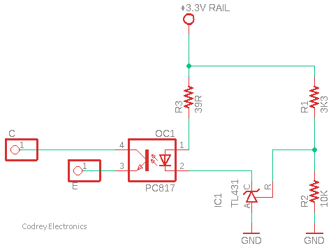
The key parts in the given schematic are the TL431 programmable zener (IC1) and the PC817 optocoupler (OC1). Since the TL431 shunt regulator lends itself very well to optocoupler control, the basic design can of course be modified for different rail voltages. Just note that when the reference input (R) of the TL431 exceeds 2.5V, it sinks current from its cathode (K).
Not to mention, the power supply rail voltage feedback is generated by the TL431 and fed into the optocoupler PC817. The resistors R1 and R2 form a voltage divider so that if the power supply rail voltage goes above 3.3V, the TL431 reference input will be above 2.5V and the TL431 conducts to energize the PC817 optocoupler.
In essence, the open-collector output of the PC817 optocoupler is an NPN bipolar junction transistor. When an NPN bipolar junction transistor is operated in the open-collector (o/c) configuration, it is operated between being fully-on, or fully-off, thus acting as an electronic solid-state switch. An open-collector output is very useful for switching incompatible loads but may require a pull-up (or pull-down) resistor to ensure the correct switching action.
Pull-up and pull-down resistors are components added to ensure a known voltage level before they are actively driven. Pull-ups pull the voltage level up to VCC (+V) when the pin is not active, while pull-downs pull the voltage down to GND (0V), thus prevents the pin from floating. Obviously, choosing between pull-up resistors and pull-down resistors often depends on the specific requirements of your design.
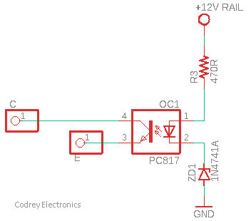
Next is another simpler approach that replaces the TL431 programmable zener chip with a 1N4741A standard zener diode (ZD1). A 12V DC power supply rail is observed this time, but this circuit can also be modified for other voltages.
Actually, these are just a couple of quick design ideas, not really intended for anything specific. I was going for a sort of minimum number of parts to do the job, without actually using readymade modules, but feel free to offer suggestions on how it could be improved.
Before closing this short note, I would like to share a few worthy pointers about the TL431 used in our first design concept.
- The TL431 is a fairly easy to use component, but it can be a bit more perplexed in its entire operation than a quick glance at an application example suggests
- For newbies, the TL431 mostly cannot pull its cathode (K) below the reference (R) voltage (~2.495V for the standard version) – some newer types can, though. Also, there are splendid 1.2V reference versions great for power supply rail voltages below 2.5V
- The optocoupler’s LED circuit must supply enough quiescent current to allow the TL431 to operate properly. In the standard version this is 400uA (absolute minimum) but a seasoned design designer might set it to around 1mA
- It is okay to add a resistor across the opto-LED for slightly better quiescent current management (and to hasten its turn-off)
- A future post will cover the application of the TL431 in SMPS circuits
With this, we have reached the end of this little post. Happy tinkering!