This is an extension of an article published here some time ago (Discrete Linear Voltage Regulator). At this point let us dive a little deeper into the design concepts of the far-famed linear voltage regulators.
Linear Voltage Regulator
Linear power supplies are the simplest of the DC-DC converters. Still, apparently simple linear voltage regulators are used much more often than complex switching power supplies.
The linear voltage regulator is the archetype of the step-down regulating power supply. It relies upon the variable conductivity of an active electronic component to drop an unregulated DC input voltage to a regulated DC output voltage.
There are two types of linear voltage regulators – the shunt regulator and the series-pass regulator. The shunt regulator is a voltage regulator that is placed in parallel with the load whereas the series-pass regulator uses an active semiconductor operates in the linear mode as the series-pass element between the input source and the output load.
Basic Series-Pass Regulator
The following example depicts a basic discrete bipolar series-pass regulator. It appears pretty simple but do not be fooled by the ostensible simplicity of the design. There are several key factors to consider (like thermal design, output regulation, overall stability, etc) any of which could cause the linear regulator circuitry to behave badly!
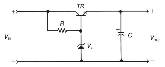
Here, the minimum input voltage (Vin) should be 2.5V more than the required output voltage (Vout). Similarly, the voltage of the zener diode (Vz) should be 0.6V higher than the output voltage (Vout).
The textbook formula for calculating the biasing resistor value (R) is shown below.
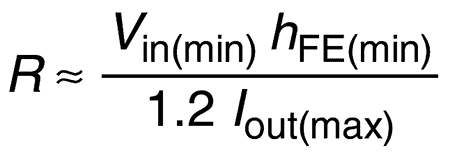
Note, IOUT is the maximum output current and hFE is the dc current gain or beta (β) of the series-pass transistor (TR).
Obviously, the transistor (TR) in this circuit controls the output voltage, and all the current delivered to the load passes through it. So, the transistor should be sized to meet the demands of the ‘headroom loss’ and the load.
The power dissipated in the transistor is (Vin-Vout) ILOAD, where ILOAD is the rated load current.
In other words, the headroom voltage is the actual voltage drop between the input voltage and the output voltage during operation.
Therefore, (Vin(max) – Vout) ILOAD(rated) is the headroom loss!
This linear series-pass fixed voltage regulator circuit will provide a reasonable degree of consistency. The low components count does not allow for temperature compensation, overcurrent protection, etc., but for most cases it gets the job done.
Note at this point that an ideal voltage-regulated power supply has zero output impedance so that the output voltage remains constant for any load current demands, but it cannot be achieved to the full in real-world. Also, semiconductor device characteristics place limits on the voltage and current that can be catered to the load.
Quick Voltage Regulator Build
When designing a regulated power supply, we usually would want to employ an easy-to-handle voltage regulator chip whenever possible, as such dedicated ICs often provide many cool features such as current limiting, short-circuit protection, etc.
However, you will often come across a custom-designed linear voltage regulator built with discrete electronics components. This could be in a vintage piece of equipment, or merely due to the fact that a non-standard voltage, or odd design specification is demanded.
So, below shown is a practical linear fixed voltage regulator circuit for your elementary experiments. Hopefully this build attempt will give you more experience in designing and making real electronic circuits.
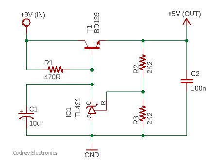
Now keep note of the following pointers:
- VIN (minimum) = VOUT + VBE of T1
- VOUT(minimum) = VREF
- VOUT = (1 + R2/R3) VREF (Typical VREF = 2.495)
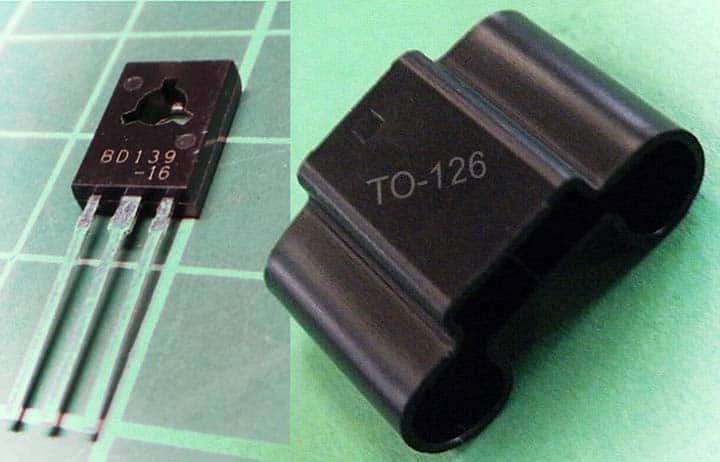
Does your pass transistor need a heatsink?
After checking out this in-depth article (Choosing a heatsink), you might be able to decide for yourself. I could not have said it better.
Wrap-Up
This post is intended to explicate things so others can get a grasp at analog electronics. While the explanations may not be helpful to you, it might be useful to some middle schoolers.
Well, good luck with the experimentations and I am happy to help or answer questions. See you then!