In the present world, different types of relays are used in the electrical home appliances and line conditioning circuits. Some of them are latching relays, reed relays, power relays, thermal relays and high voltage relays.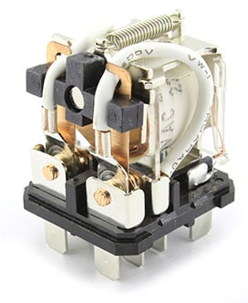
By definition, Electrical Relay is a switching device that can be used to open or close the contacts electrically. It is an automatic switch when excited with an input signal changes the output circuit quickly.
The input signal may be heat, light, electricity and magnetism. The output circuit consists of contacts to turn on loads or actuators. The input section (control circuit) and output section (contacts circuit or load circuit) are isolated by signal transfer. A strong signal energizes the relay and a weak signal de-energizes the relay.
Types of Relays
Generally, there are two types of relays used for DC and AC switching: Electromechanical and Solid-state relays. In this article, we will see the further classification of relays based on principle and structure.
- Electromechanical Relays
- Electromagnetic attraction type relay
- Attraction armature type relay
- Solenoid type relay
- Balanced beam-type relay
- Electromagnetic induction type relay
- Shaded Pole type structure
- Watthour-meter type structure
- Induction Cup type structure
- Electromagnetic attraction type relay
- Solid State relays
-
Electromechanical relays
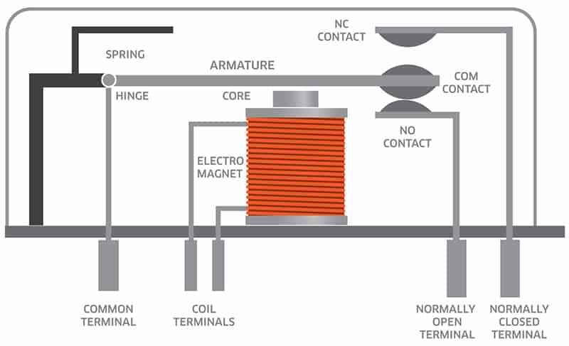
This is a conventional type of relay. It uses an electromagnet to turn ON or OFF the circuits. Most of the relays are used to protect the system in power system industries which are operated by current or voltage. Based on the construction principle, relay types are:
- Electromagnetic attraction type relay
- Electromagnetic induction type relay
-
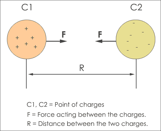
Electromagnetic Attraction type relay
Electromagnetic attraction relays can be actuated by both AC & DC quantities. It can be operated by the movement of a piece of iron (electromagnet) when it is attracted by the magnetic field produced by a coil or a plunger being drawn into a solenoid. Based on this principle of electromagnetic these are classified into:
- Attraction armature type relay
- Solenoid type relay
- Balanced beam-type relay
-
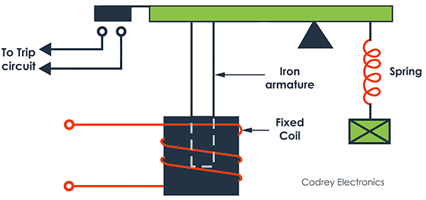
Attraction Armature type
This relay type consists of a plate made of iron that pivots when it is attracted towards the coil. Here letter ‘M’ represents the electromagnet and the letter ‘C’ is the coil. The armature is balanced by a counterweight and a spring at its end.
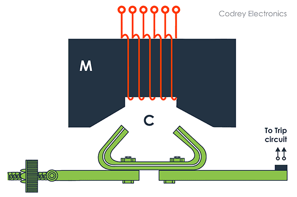
Under normal operating conditions, the counterweight holds the armature of the above position shown in the figure when the current is passed through the coil. When a short circuit occurs, the current through the coil increases sufficiently and the armature attracted upwards. The contacts on the armature bridge a pair of stationary contacts attached to the relay frame. This completes the trip circuit which opens the circuit breaker and disconnects the faulty circuit. The minimum current at which the relay armature is attracted to close the trip circuit is called pickup current.
-
Solenoid Type Relay
It consists of a solenoid (electromagnetic coil) with a hollow center core and movable iron plunger. Here plunger carries the moving contact. The plunger is used to attract axially within the field of the solenoid. Under normal conditions, the current through the coil that it holds the plunger by gravity or spring in the position. When the magnet is energized, the plunger attracted to the solenoid moves up and down through the core.
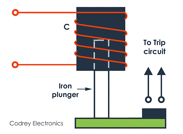
The upward movement of the plunger closes the circuits. On the occurrence of a fault, the current through the coil increases (more than pickup current), the plunger is attracted to the solenoid. Here the upward movement of the plunger closes the trip circuit which opens the circuit breaker and disconnects the faulty circuit.
-
Balanced Beam-Type Relay
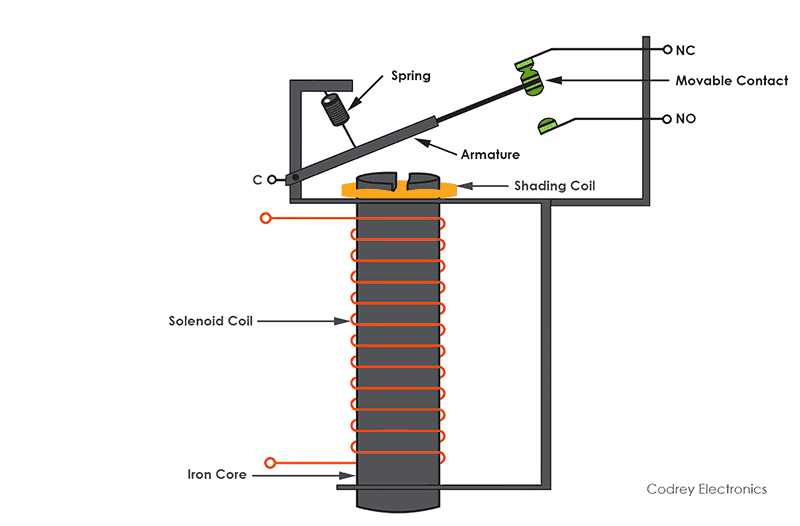
It consists of an iron armature fastened to a balance beam. Under normal operating conditions, the current through the relay coil is such that the beam is held in the horizontal position by the spring.
When a fault occurs, the current through the relay coil becomes greater than the pickup value and the beam is attracted to close the trip circuit and causes the opening of the circuit breaker to isolate the faulty circuit.
-
Electromagnetic Induction type relay
An Induction type of relays works only with AC. It consists of a pivoted aluminium disc or cup placed in two alternating magnetic fields of the same frequency but displaced in time and space. It operates on a moving conductor in the form of a rotor or disc. These are widely used for protective relaying purposes.
Electromagnetic-induction relays operate on the principle of induction motor where torque is developed by the interaction of one of the magnetic fields with the current induced in the rotor or disc.
There are three types of induction relays based on the structures and used for obtaining the phase-difference and hence the operating torque in induction relays. They are:
- Shaded pole type structure
- Watthour-meter type structure
- Induction Cup type structure
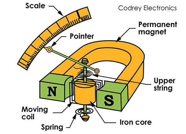
- Shaded Pole Type Structure
The disc is made up of aluminium. The one half of each pole of the electromagnet is surrounded by a copper band is called shading ring. The coil is energized by current flowing in a single-coil wound on a magnetic structure containing an air gap. The disc is free to rotate in an air gap.
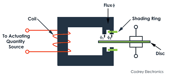
The shaded portion of the pole produces a flux that is displaced in space and time w.r.t the flux produced by an unshaded portion of the pole. These two alternating fluxes cut disc and produce eddy currents. Torques are produced by the interaction of each flux with the eddy current produced by the other flux. The resultant torque causes the disc to rotate.
- Watthour-Meter Type Structure
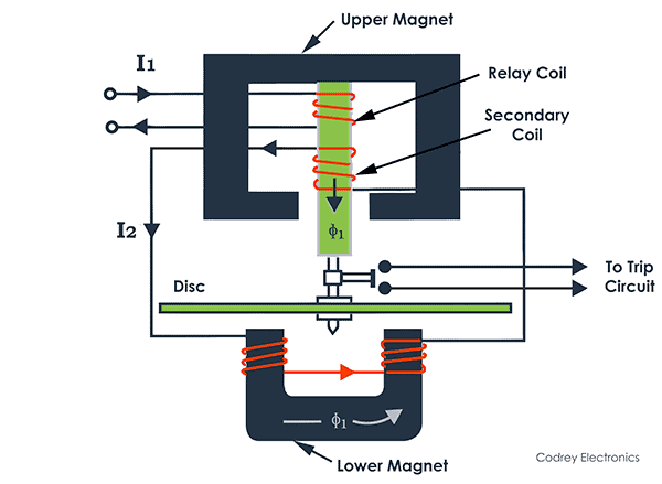
This structure gets its name from the fact that it is used in watt-hour meters. It consists of an E-shaped electromagnet (upper) carries two windings; the primary and the secondary coils, while the secondary coil is connected to a U-shaped electromagnet (lower). There is a disc between the two electromagnets is free to rotate. Each of the magnetic circuits produces one of two necessary fluxes for driving the rotor, which is also a disc.
Each magnet produces an alternating flux which cuts the disc. To obtain a phase displacement between two fluxes produced by upper and lower electromagnets, their coil may be energized by two different sources.
If they are energized by the same source, the resistance and reactance of the two circuits are made different so that there will be sufficient phase difference.
The primary winding carries relay current I. The primary current induces emf in the secondary and so circulates a current I2 in it. The flux ɸ2induced in the U-shaped(lower) magnet by the current in the secondary winding of the E-shaped(upper) magnet will lag behind flux ɸ1 by an angle θ. The two fluxes ɸ1 and ɸ2 induced in upper and lower magnets respectively differing in phase by angle θ will develop a driving torque on the disc proportional to ɸ1. ɸ2 sin θ.
An important feature of this relay is that its operation can be controlled by opening or closing the secondary winding circuit. If this circuit is opened, no torque will be developed and thus the relay can be made inoperative.
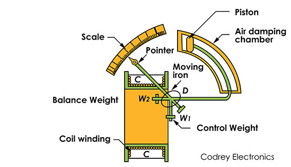
- Induction Cup Type Structure
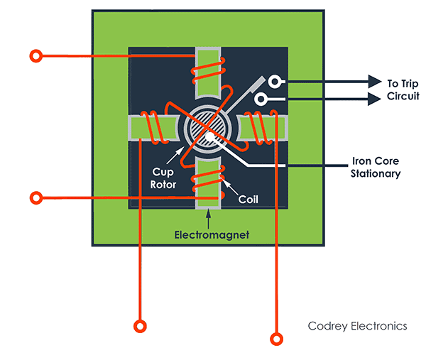
This types of relays work on the same principle of induction motor. The relay has two, four or more electromagnets energized by the relay coils. A stationary iron core is placed between these electromagnets to decrease the air gap without increasing inertia. The rotor is a hollow metallic cylindrical cup which is free to rotate in the gap between the electromagnets and the stationary iron core
The rotating field is produced by two pairs of coils wound on four poles. The rotating field induces currents in the cup causing it to rotate in the same direction.
The rotation depends on the direction of rotation of the field and the magnitude of the applied voltage or currents and the phase angle between them. Control spring and the backstop or closing of the contacts carried on an arm are attached to the spindle of the cup to prevent the continuous rotation.
Induction cup structures are more efficient torque producers than either the shaded-pole or the watt-hour-meter structures.
Advantages of Electromechanical relays
- Simple, robust and compact
- Cost is low
- High operating speed
- Can be used for both AC & DC systems
- Can withstand high voltages
- It provides physical isolation between the load and control circuit in applications where a circuit must be completed on or off with minimal voltage drop or to provide damage from leakage current.
Disadvantages of Electromechanical relays
- Generates noise due to its mechanical parts
- Limited lifetime
- It is slow because of the mechanical parts when compared to semiconductor-based relays
Applications:
Here are some applications of electromechanical relays.
- Used for the protection of various AC and DC equipment
- Motor control and automotive applications
- To control large power loads in industrial applications
-
Solid-State Relays
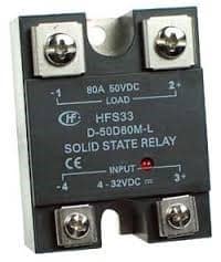
A solid-state relay(SSR) is an electronic switching device that switches on or off when a small external voltage is applied across its control terminals. It does not have a moving contact like electromechanical relays. The SSR consists of semiconductor switching elements such as diodes, Triacs, transistors, and thyristors. It normally uses TRIAC or Thyristors for AC circuit & Power MOSFETs for the DC circuit. Modern type solid-state relays are capable of handling higher levels of voltage than older relays.
Working Principle:
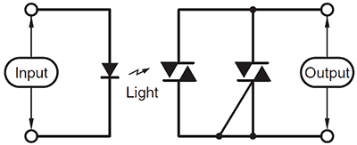
When a switch is turned ON, current flows to the input circuits, it turns on the LED. It emits infrared light and it illuminates the photosensitive device which may be diode or TRIAC or transistor. Here LED and photosensitive device forms an optocoupler or optoisolator which transfers an electrical signal between two isolated circuits by light. The diode current turns on a back-to-back TRIAC, thyristor, SCR, or MOSFET to switch the load.
Advantages of Solid-State Relays
- Faster switching speeds
- No physical contacts to wear out.
- There are no mechanical parts and thus noiseless
- Lifetime is higher
- Greater resistance to vibration or shock
- Useful for high-voltage applications
Disadvantages of Solid-State Relays
- They are not robust
- More expensive
- Dissipate more heat
- They are highly susceptible to surge currents and damage when used at signal levels above their rating
Solid State Relay Applications:
- widely used for switching DC and AC circuits.
- Used in process control industries, communication lines, power switching, etc.
- These can be used as a latch in kettles, where an input pulse would indicate a start, and latch onto that state until it is interrupted
- Used to control power for an eg. light/fan dimming, motor speed control, to drive heaters to control the temperature
- Non-Polarized Power relays are used in cooking and HVAC controls (In Duct flow boost fans, Air purification, Blowers, CNC machines, etc.)
- High-Frequency relays are used in Broadcasting
Conclusion
Different types of relays exist in the market with necessary Trigger Voltage (Turn on the time required for the relay to change the contact from NC to NO. Also, there are different kinds of relay based on coil voltages such as 3V, 5V, 6V, and 12V. You can select the required relay based on the project.
Recently, relays are coming with optocoupler or semiconductors known as PhotoMOS types of relays which overcomes the conventional electromechanical technology. The advantage of PhotoMOS relays is longer lifetime, stable behavior in harsh environments, high switching speed.
If you have an interest in saving power, then latching bistable relays are used. Most importantly, they eliminate coil suppression and transient suppression in DC circuits.